02Connecting up
+6Chapter 2
Connecting up
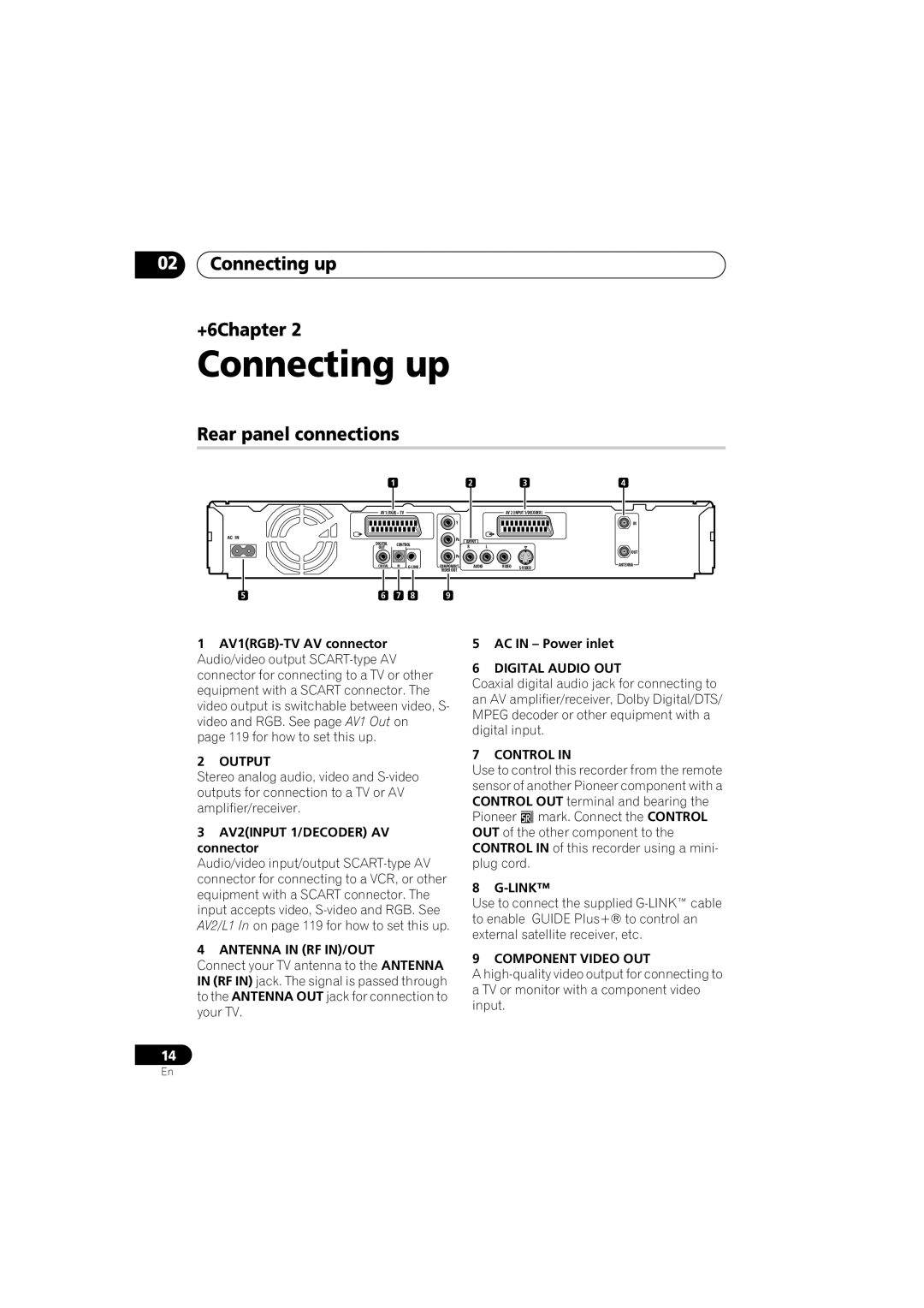
Rear panel connections
|
| 1 |
|
| 2 |
| 3 | 4 |
| AV 1 (RGB) – TV |
|
|
| AV 2 (INPUT 1/DECODER) |
| ||
|
|
|
| Y |
|
|
| IN |
AC IN |
|
|
| PB | OUTPUT |
|
|
|
| DIGITAL |
|
|
|
|
| ||
| CONTROL |
| R | L |
|
| ||
| OUT |
|
|
|
| OUT | ||
|
|
|
| PR |
|
|
| |
|
|
|
|
|
|
|
| |
| COAXIAL | IN | COMPONENT | AUDIO | VIDEO | ANTENNA | ||
|
|
|
| VIDEO OUT |
|
|
|
|
5 | 6 | 7 | 8 | 9 |
|
|
|
|
1
2OUTPUT
Stereo analog audio, video and
3AV2(INPUT 1/DECODER) AV connector
Audio/video input/output
4ANTENNA IN (RF IN)/OUT
Connect your TV antenna to the ANTENNA IN (RF IN) jack. The signal is passed through to the ANTENNA OUT jack for connection to your TV.
5AC IN – Power inlet
6DIGITAL AUDIO OUT
Coaxial digital audio jack for connecting to an AV amplifier/receiver, Dolby Digital/DTS/ MPEG decoder or other equipment with a digital input.
7 CONTROL IN
Use to control this recorder from the remote sensor of another Pioneer component with a CONTROL OUT terminal and bearing the Pioneer mark. Connect the CONTROL OUT of the other component to the CONTROL IN of this recorder using a mini- plug cord.
8 G-LINK™
Use to connect the supplied
9 COMPONENT VIDEO OUT
A
14
En