Chapter 2 - Hardware Description
MGC Unit Components
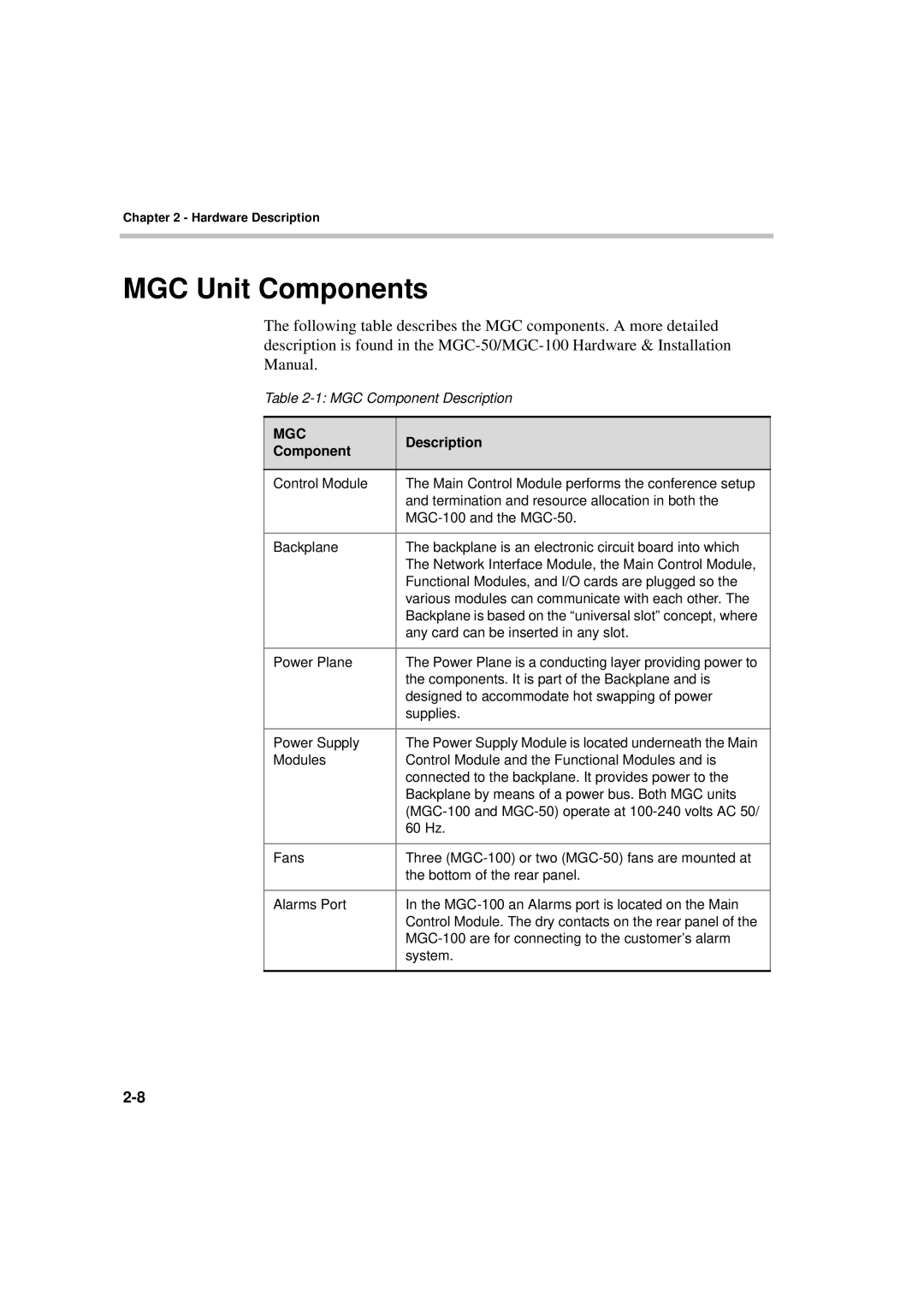
The following table describes the MGC components. A more detailed description is found in the
Table
MGC | Description | |
Component | ||
| ||
|
| |
Control Module | The Main Control Module performs the conference setup | |
| and termination and resource allocation in both the | |
| ||
|
| |
Backplane | The backplane is an electronic circuit board into which | |
| The Network Interface Module, the Main Control Module, | |
| Functional Modules, and I/O cards are plugged so the | |
| various modules can communicate with each other. The | |
| Backplane is based on the “universal slot” concept, where | |
| any card can be inserted in any slot. | |
|
| |
Power Plane | The Power Plane is a conducting layer providing power to | |
| the components. It is part of the Backplane and is | |
| designed to accommodate hot swapping of power | |
| supplies. | |
|
| |
Power Supply | The Power Supply Module is located underneath the Main | |
Modules | Control Module and the Functional Modules and is | |
| connected to the backplane. It provides power to the | |
| Backplane by means of a power bus. Both MGC units | |
| ||
| 60 Hz. | |
|
| |
Fans | Three | |
| the bottom of the rear panel. | |
|
| |
Alarms Port | In the | |
| Control Module. The dry contacts on the rear panel of the | |
| ||
| system. | |
|
|
