Chapter 2 - Hardware Description
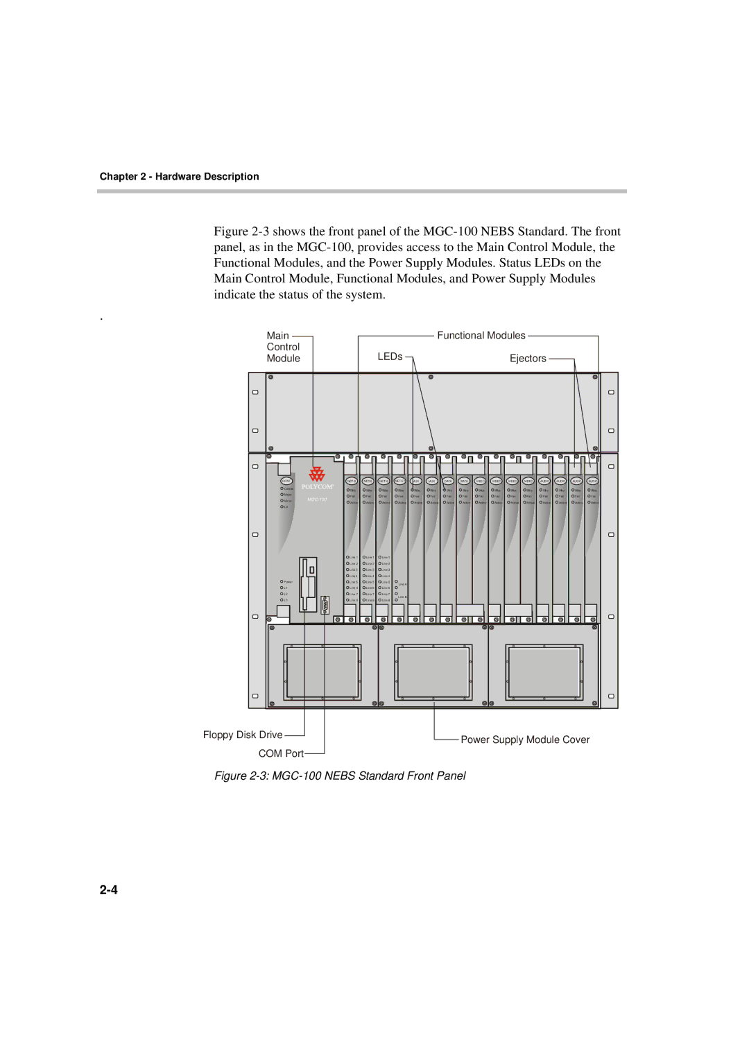
Figure 2-3 shows the front panel of the MGC-100 NEBS Standard. The front panel, as in the MGC-100, provides access to the Main Control Module, the Functional Modules, and the Power Supply Modules. Status LEDs on the Main Control Module, Functional Modules, and Power Supply Modules indicate the status of the system.
.
| Main |
|
|
| Functional Modules |
|
|
|
|
|
|
|
|
| |||
| Control |
| LEDs |
|
|
|
| |
|
| Ejectors |
| |||||
| Module |
|
| |||||
|
|
|
|
|
|
|
|
|
|
|
|
|
|
|
|
|
|
CONT |
| MUX | MUX | DATA | DATA | VIDEO | VIDEO | VIDEO | VIDEO | AUDIO | AUDIO | AUDIO | AUDIO | ||||
Critical |
| Stby | Stby | Stby | Stby | Stby | Stby | Stby | Stby | Stby | Stby | Stby | Stby | Stby | Stby | Stby | Stby |
Major |
| Fail | Fail | Fail | Fail | Fail | Fail | Fail | Fail | Fail | Fail | Fail | Fail | Fail | Fail | Fail | Fail |
| |||||||||||||||||
Minor | Active | Active | Active | Active | Active | Active | Active | Active | Active | Active | Active | Active | Active | Active | Active | Active | |
|
| ||||||||||||||||
L0 |
|
|
|
|
|
|
|
|
|
|
|
|
|
|
|
|
|
|
| Line 1 | Line 1 | Line 1 |
|
|
|
|
|
|
|
|
|
|
|
|
|
|
| Line 2 | Line 2 | Line 2 |
|
|
|
|
|
|
|
|
|
|
|
|
|
|
| Line 3 | Line 3 | Line 3 |
|
|
|
|
|
|
|
|
|
|
|
|
|
|
| Line 4 | Line 4 | Line 4 |
|
|
|
|
|
|
|
|
|
|
|
|
|
Power |
| Line 5 | Line 5 | Line 5 | Line A |
|
|
|
|
|
|
|
|
|
|
|
|
L1 |
| Line 6 | Line 6 | Line 6 |
|
|
|
|
|
|
|
|
|
|
|
| |
|
|
|
|
|
|
|
|
|
|
|
|
|
| ||||
L2 |
| Line 7 | Line 7 | Line 7 | Line B |
|
|
|
|
|
|
|
|
|
|
|
|
L3 |
| Line 8 | Line 8 | Line 8 |
|
|
|
|
|
|
|
|
|
|
|
| |
|
|
|
|
|
|
|
|
|
|
|
|
|
|
Floppy Disk Drive |
|
|
| Power Supply Module Cover | ||
|
| |||||
COM Port |
|
|
|
| ||
|
|
|
|
| ||
|
|
|
| |||