Chapter 4 - Hardware Description

The Net-E1/Net-T1 ISDN Network Interface Data Stream

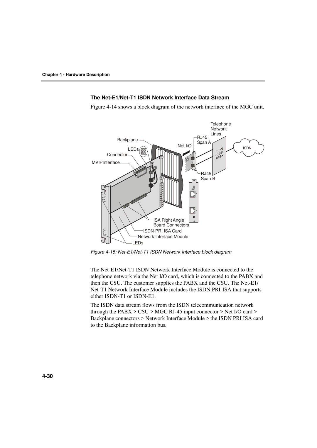
Figure 4-14 shows a block diagram of the network interface of the MGC unit.


Telephone


Network

Backplane


RJ45

Lines


Span A


Net I/O

LEDs


ISDN


Connector


MVIPInterface

RJ45

Span B

NET

A

B

ISA Right Angle

Board Connectors

ISDN-PRI ISA Card

Network Interface Module

LEDs

Figure 4-15: Net-E1/Net-T1 ISDN Network Interface block diagram

The Net-E1/Net-T1 ISDN Network Interface Module is connected to the telephone network via the Net I/O card, which is connected to the PABX and then the CSU. The customer supplies the PABX and the CSU. The Net-E1/ Net-T1 Network Interface Module includes the ISDN PRI-ISA that supports either ISDN-T1 or ISDN-E1.

The ISDN data stream flows from the ISDN telecommunication network through the PABX > CSU > MGC RJ-45 input connector > Net I/O card > Backplane connectors > Network Interface Module > the ISDN PRI ISA card to the Backplane information bus.
4-30

Page 104
Image 104
Polycom MGC-50/MGC-100 installation manual Net-E1/Net-T1 Isdn Network Interface Data Stream