Polycom MGC-50/MGC-100 installation manual Pwr

Models: MGC-50/MGC-100

1 172
Download 172 pages 45.37 Kb
Page 159
Image 159

MGC Hardware and Installation Manual

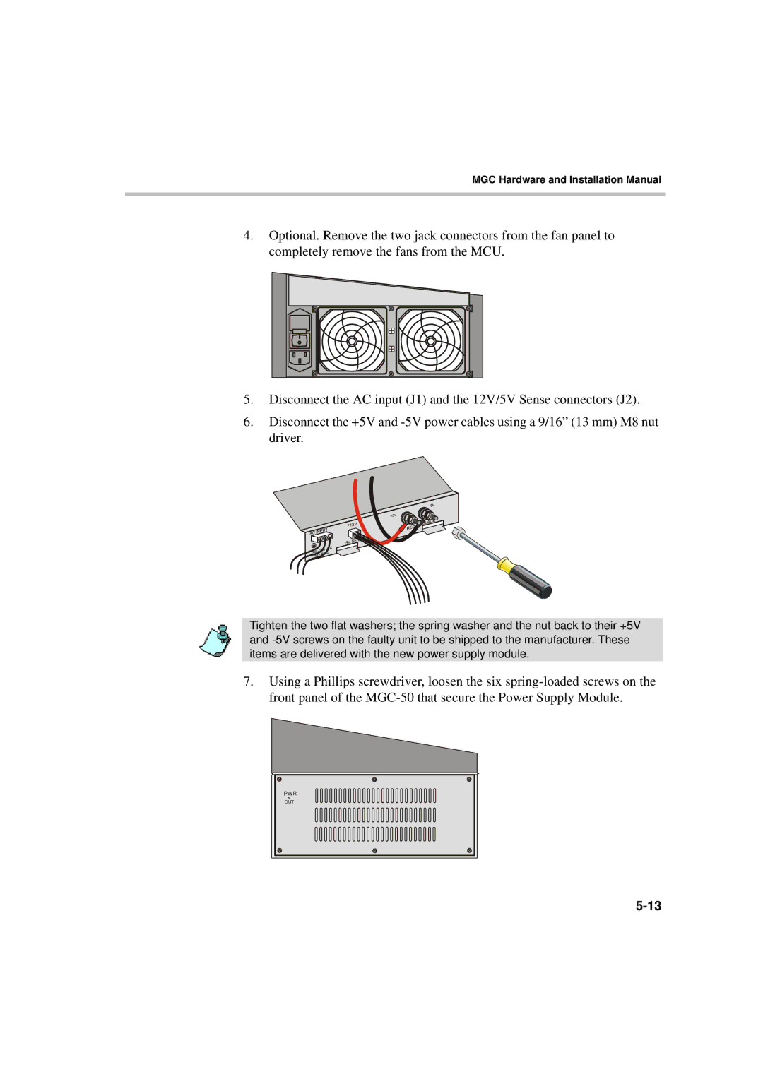
4.Optional. Remove the two jack connectors from the fan panel to completely remove the fans from the MCU.

5.Disconnect the AC input (J1) and the 12V/5V Sense connectors (J2).

6.Disconnect the +5V and -5V power cables using a 9/16” (13 mm) M8 nut driver.

Tighten the two flat washers; the spring washer and the nut back to their +5V and -5V screws on the faulty unit to be shipped to the manufacturer. These items are delivered with the new power supply module.

7.Using a Phillips screwdriver, loosen the six spring-loaded screws on the front panel of the MGC-50 that secure the Power Supply Module.

PWR

OUT

5-13

Page 159
Image 159
Polycom MGC-50/MGC-100 installation manual Pwr