Chapter 5 - System Maintenance
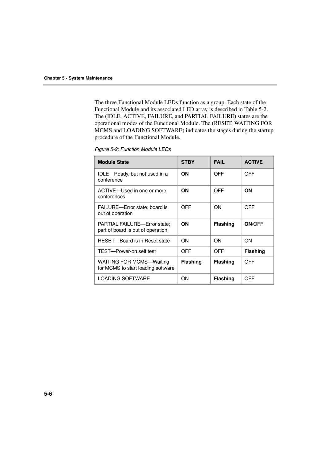
The three Functional Module LEDs function as a group. Each state of the Functional Module and its associated LED array is described in Table
Figure 5-2: Function Module LEDs
Module State | STBY | FAIL | ACTIVE |
|
|
|
|
ON | OFF | OFF | |
conference |
|
|
|
|
|
|
|
ON | OFF | ON | |
conferences |
|
|
|
|
|
|
|
OFF | ON | OFF | |
out of operation |
|
|
|
|
|
|
|
PARTIAL | ON | Flashing | ON/OFF |
part of board is out of operation |
|
|
|
|
|
|
|
ON | ON | ON | |
|
|
|
|
OFF | OFF | Flashing | |
|
|
|
|
WAITING FOR | Flashing | Flashing | OFF |
for MCMS to start loading software |
|
|
|
|
|
|
|
LOADING SOFTWARE | ON | Flashing | OFF |
|
|
|
|