Chapter 2 - Hardware Installation
8.Place the MCU in a 23” rack and while supporting it, screw the mounting brackets to the rack securing it with bolts and
When the unit is installed on a rack, the rack must be properly grounded to the central office ground. The rack must be grounded with
Mounting the MGC-100 on a 19” Rack
The
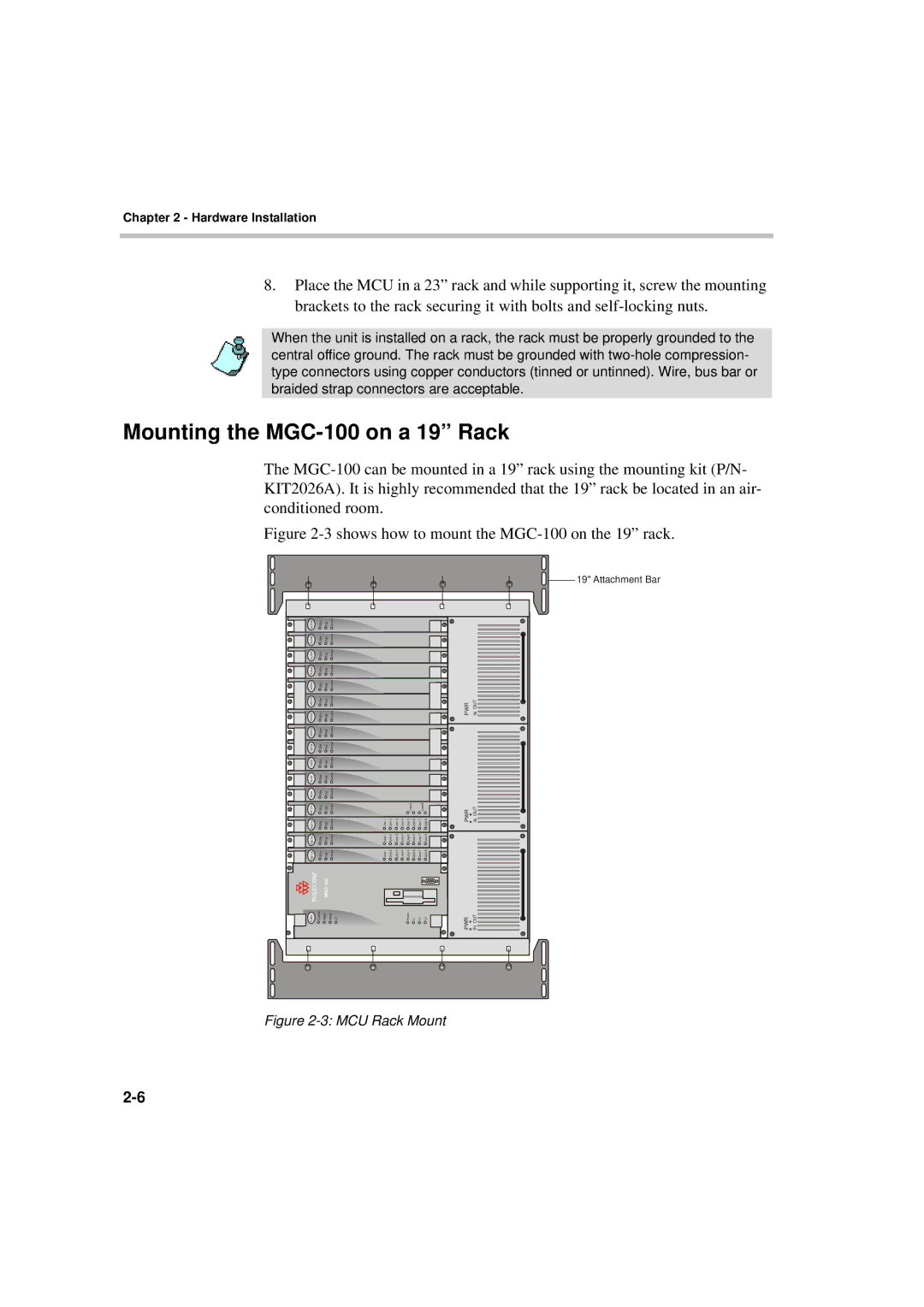
Figure 2-3 shows how to mount the MGC-100 on the 19” rack.

 19" Attachment Bar
AUDIO | Stby | Fail | Active |
|
|
|
|
|
|
|
|
|
|
|
AUDIO | Stby | Fail | Active |
|
|
|
|
|
|
|
|
|
|
|
AUDIO | Stby | Fail | Active |
|
|
|
|
|
|
|
|
|
|
|
AUDIO | Stby | Fail | Active |
|
|
|
|
|
|
|
|
|
|
|
VIDEO | Stby | Fail | Active |
|
|
|
|
|
|
|
|
|
|
|
VIDEO VIDEO | Stby Stby | Fail Fail | Active Active |
|
|
|
|
|
|
|
|
| PWR | IN OUT |
VIDEO | Stby | Fail | Active |
|
|
|
|
|
|
|
|
|
|
|
DATA | Stby | Fail | Active |
|
|
|
|
|
|
|
|
|
|
|
DATA | Stby | Fail | Active |
|
|
|
|
|
|
|
|
|
|
|
MUX | Stby | Fail | Active |
|
|
|
|
|
|
|
|
|
|
|
MUX | Stby | Fail | Active |
|
|
|
|
|
|
|
|
|
|
|
Stby Stby | Fail Fail | Active Active |
|
|
|
|
| Line A |
| Line 7 Line B Line 8 | PWR | IN OUT | ||
| Line 1 | Line 2 | Line 3 | Line 4 | Line 5 | Line 6 | ||||||||
Stby | Fail | Active |
| Line 1 | Line 2 | Line 3 | Line 4 | Line 5 | Line 6 | Line 7 | Line 8 |
|
| |
Stby | Fail | Active |
| Line 1 | Line 2 | Line 3 | Line 4 | Line 5 | Line 6 | Line 7 | Line 8 |
|
| |
CONT | Critical | Major | Minor | L0 |
|
|
|
| Power | L1 | L2 | L3 | PWR | IN OUT |
