Chapter 3 - System Architecture
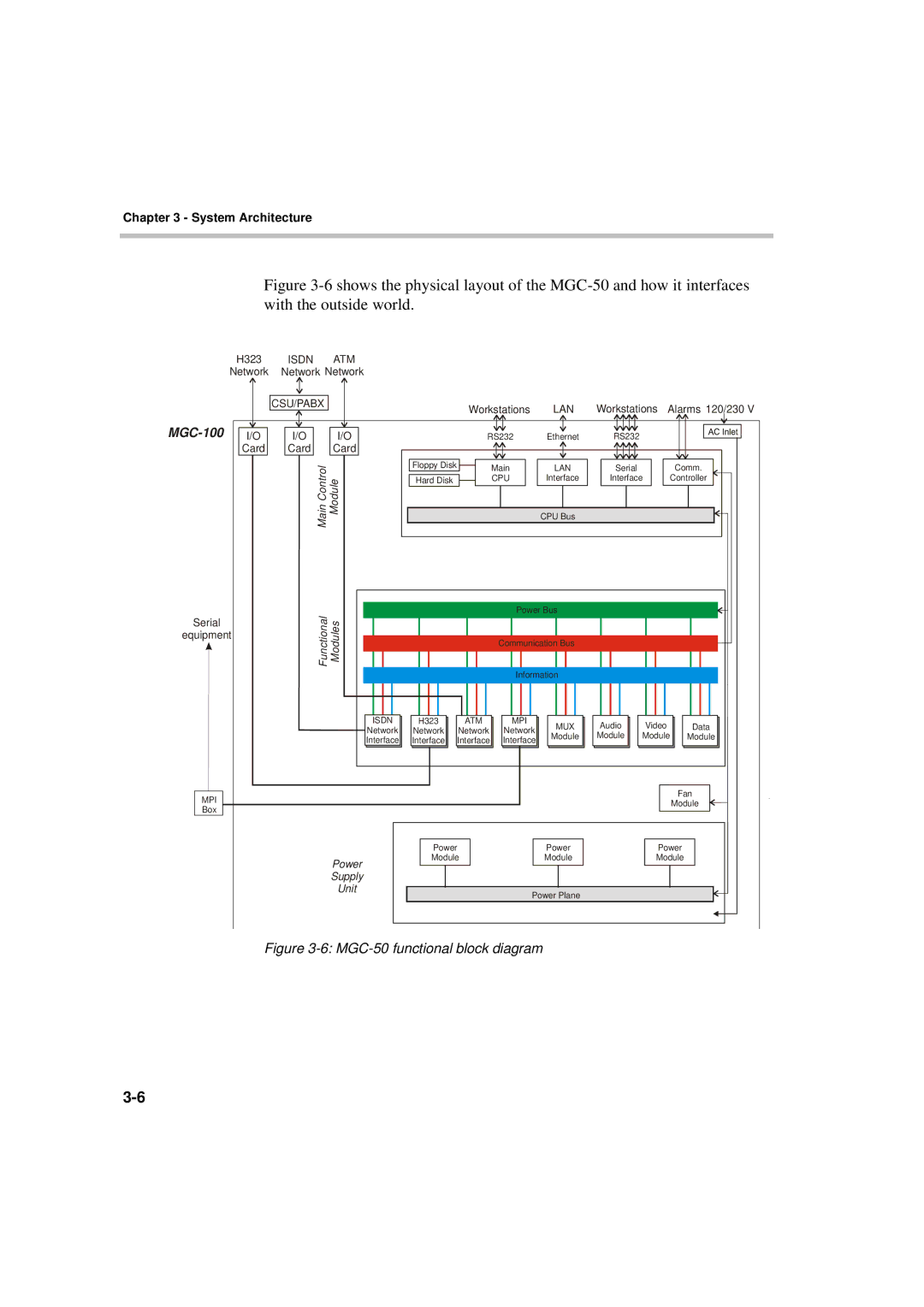
Figure 3-6 shows the physical layout of the MGC-50 and how it interfaces with the outside world.
| H323 |
| ISDN | ATM |
|
|
|
|
|
|
|
| ||||||||
| Network | Network Network |
|
|
|
|
|
|
|
| ||||||||||
|
|
|
|
|
|
|
|
|
|
|
|
|
|
|
|
|
|
|
|
|
|
|
|
|
|
|
|
|
|
|
|
|
|
|
|
|
|
|
|
| |
|
|
|
| CSU/PABX |
|
|
|
|
|
| Workstations | LAN | ||||||||
|
|
|
|
|
|
|
|
|
|
|
|
|
| |||||||
|
|
|
|
|
|
|
|
|
|
|
|
|
|
|
|
|
| |||
| I/O |
| I/O |
| I/O |
|
|
| RS232 | Ethernet | ||||||||||
|
| Card |
| Card |
| Card |
|
|
|
|
|
|
|
|
|
|
| |||
|
|
|
|
|
|
|
|
|
| |||||||||||
|
|
|
|
|
|
|
|
|
|
|
|
|
|
|
|
|
|
|
|
|
|
|
|
|
|
|
| ControlMain |
|
|
|
|
| Floppy Disk |
| Main |
| LAN | |||
|
|
|
|
|
|
|
|
|
|
|
|
|
| |||||||
|
|
|
|
|
|
| Module |
|
|
|
| CPU |
| Interface | ||||||
|
|
|
|
|
|
|
|
|
|
|
|
| Hard Disk |
|
| |||||
|
|
|
|
|
|
|
|
|
|
|
|
|
|
|
|
|
|
|
|
|
|
|
|
|
|
|
|
|
|
|
|
|
|
|
|
|
|
|
| CPU Bus | |
|
|
|
|
|
|
|
|
|
|
|
|
|
|
|
|
|
|
|
|
|
Serial | Functional Modules |
|
|
|
|
|
| Power Bus | |||
|
|
|
|
|
|
|
|
|
| ||
|
|
|
|
|
|
|
|
|
| ||
equipment |
|
|
|
|
|
|
|
|
| ||
|
|
|
|
|
| Communication Bus | |||||
|
|
|
|
|
|
| |||||
|
|
|
|
|
|
|
|
|
|
|
|
|
|
|
|
|
|
|
|
|
|
|
|
|
|
|
|
|
|
|
| Information | |||
ISDN | H323 | ATM | MPI | MUX | |
Network | Network | Network | Network | ||
Module | |||||
Interface | Interface | Interface | Interface | ||
|
MPI
Box
|
|
|
|
|
|
|
|
| Power |
| Power | ||
Power |
| Module |
| Module | ||
|
|
|
|
|
| |
Supply |
|
|
|
|
|
|
Unit |
|
|
|
|
|
|
|
|
| Power Plane | |||
|
|
|
| |||
|
|
|
|
|
|
|
Workstations Alarms 120/230 V
RS232
Serial |
| Comm. | ||
Interface |
| Controller | ||
|
|
|
|
|
|
|
|
|
|
Audio | Video | Data |
Module | Module | Module |
Fan
Module
Power
Module