MGC Hardware and Installation Manual
Information Flow
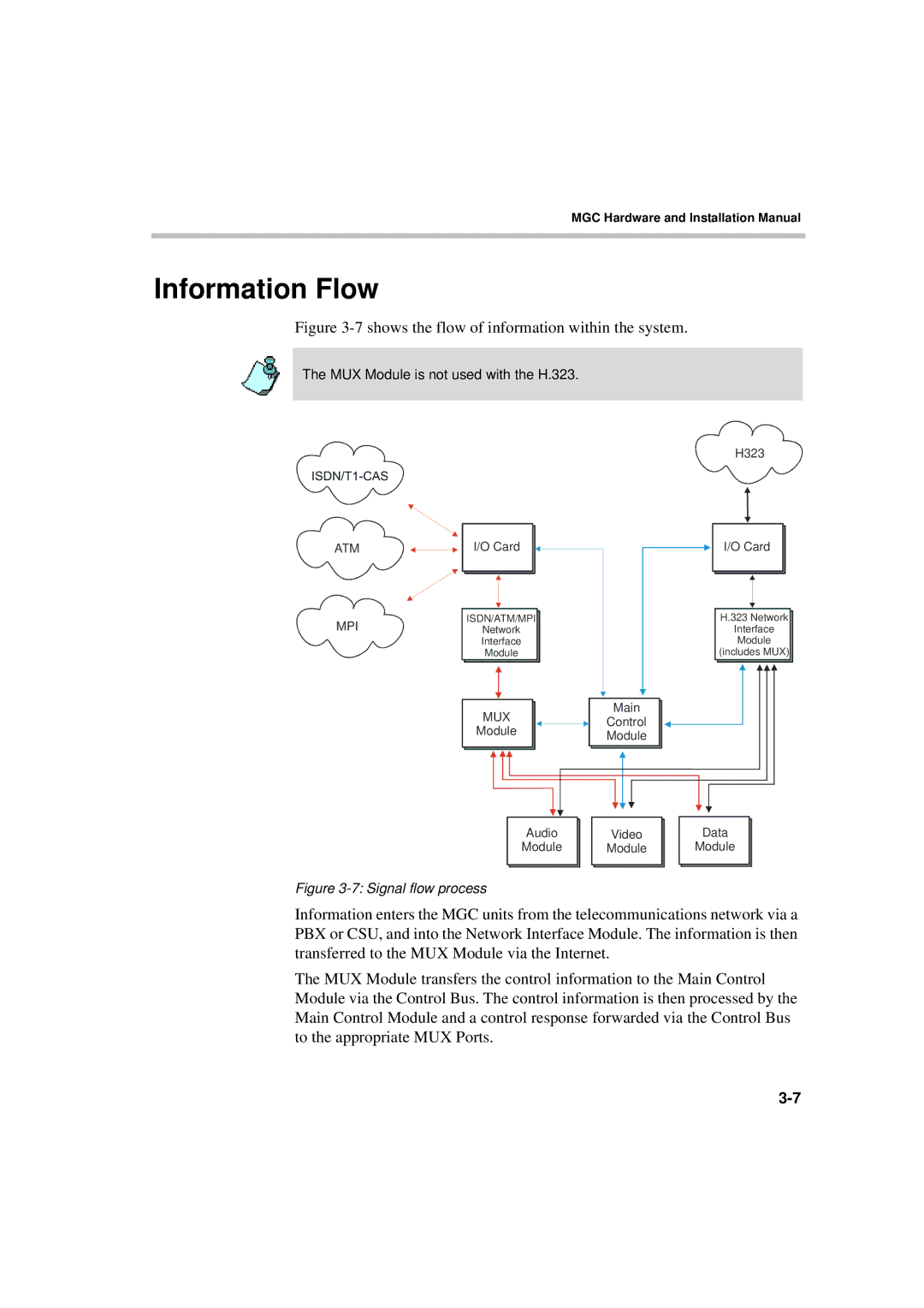
Figure 3-7 shows the flow of information within the system.
The MUX Module is not used with the H.323.
ATM | I/O Card |
|
| ||
|
| ||||
|
|
|
|
|
|
|
|
|
|
|
|
MPI |
| ISDN/ATM/MPI |
| ||
|
| ||||
| Network |
| |||
|
| Interface |
| ||
|
| Module |
| ||
|
|
|
|
|
|
|
|
|
|
|
|
|
|
|
|
|
|
MUX
Module
H323
I/O Card
H.323 Network
Interface
Module
(includes MUX)
Main
Control
Module
| Audio |
|
| Video |
|
| Data |
| Module |
|
| Module |
|
| Module |
|
|
|
|
|
|
|
|
Figure 3-7: Signal flow process
Information enters the MGC units from the telecommunications network via a PBX or CSU, and into the Network Interface Module. The information is then transferred to the MUX Module via the Internet.
The MUX Module transfers the control information to the Main Control Module via the Control Bus. The control information is then processed by the Main Control Module and a control response forwarded via the Control Bus to the appropriate MUX Ports.
