Chapter 5 - System Maintenance
Controls and Indicators
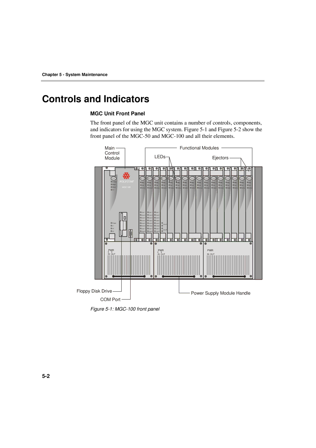
MGC Unit Front Panel
The front panel of the MGC unit contains a number of controls, components, and indicators for using the MGC system. Figure
Main
Control
Module
CONT
Critical
Major
Minor
L0
Power
L1
L2
L3
PWR
IN OUT
Floppy Disk Drive
COM Port
Functional Modules
|
| LEDs |
|
|
|
|
|
| Ejectors |
|
|
| |||
MUX | MUX | DATA | DATA | VIDEO | VIDEO | VIDEO | VIDEO | AUDIO | AUDIO | AUDIO | AUDIO | ||||
Stby | Stby | Stby | Stby | Stby | Stby | Stby | Stby | Stby | Stby | Stby | Stby | Stby | Stby | Stby | Stby |
Fail | Fail | Fail | Fail | Fail | Fail | Fail | Fail | Fail | Fail | Fail | Fail | Fail | Fail | Fail | Fail |
Active | Active | Active | Active | Active | Active | Active | Active | Active | Active | Active | Active | Active | Active | Active | Active |
Line 1 | Line 1 | Line 1 |
|
|
|
|
|
|
|
|
|
|
|
|
|
Line 2 | Line 2 | Line 2 |
|
|
|
|
|
|
|
|
|
|
|
|
|
Line 3 | Line 3 | Line 3 |
|
|
|
|
|
|
|
|
|
|
|
|
|
Line 4 | Line 4 | Line 4 |
|
|
|
|
|
|
|
|
|
|
|
|
|
Line 5 | Line 5 | Line 5 | Line A |
|
|
|
|
|
|
|
|
|
|
|
|
Line 6 | Line 6 | Line 6 |
|
|
|
|
|
|
|
|
|
|
|
| |
|
|
|
|
|
|
|
|
|
|
|
|
| |||
Line 7 | Line 7 | Line 7 | Line B |
|
|
|
|
|
|
|
|
|
|
|
|
Line 8 | Line 8 | Line 8 |
|
|
|
|
|
|
|
|
|
|
|
| |
|
|
|
|
|
|
|
|
|
|
|
|
| |||
PWR | PWR |
IN OUT | IN OUT |
Power Supply Module Handle