MGC Hardware and Installation Manual
Because of heat considerations, the MCU must be installed with the Control Unit Module placed on the left bottom.
1.Check that all the parts are in the kit.
The kit should contain the following items:
Table
Item # | Polycom P/N | Description | Quantity |
|
|
|
|
1 | MEC2063A | 23" TO 19" Mounting Bar MGC- | 2 |
|
| 100 at 90 Degrees |
|
|
|
|
|
2 | SCR2005A | Screw | 8 |
|
| ST/ST |
|
|
|
|
|
3 | WAS2003A | Washer M5 Spring Latch Loc. | 8 |
|
| ST\ST |
|
|
|
|
|
4 | WAS2004A | Washer M5 Flat ST/ST | 8 |
|
|
|
|
2.Make sure that the MCU power is turned OFF and it is disconnected from the AC and DC power.
Remove the side covers as described on page
3.If the MCU is a standalone unit, you must first remove the side covers, and add the mounting brackets to a 23” rack (see pages
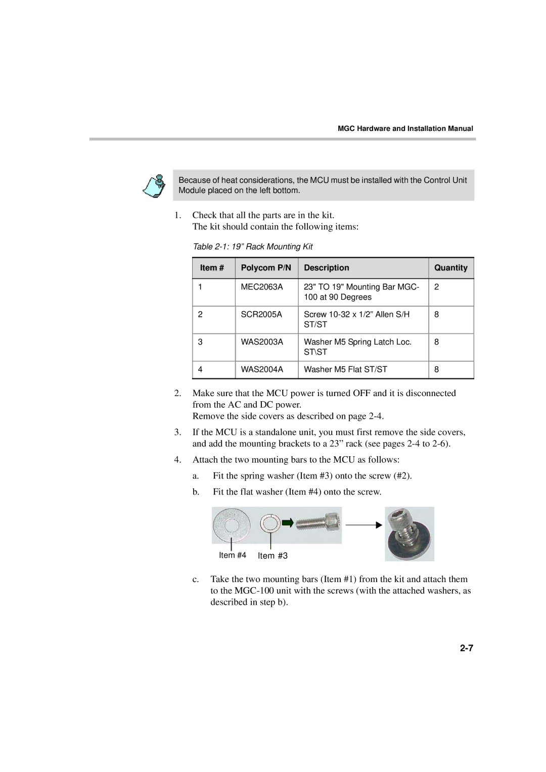
4.Attach the two mounting bars to the MCU as follows:
a.Fit the spring washer (Item #3) onto the screw (#2).
b.Fit the flat washer (Item #4) onto the screw.
Item #4 Item #3
c.Take the two mounting bars (Item #1) from the kit and attach them to the