MGC Hardware and Installation Manual
Main Switch
and Circuit Breaker
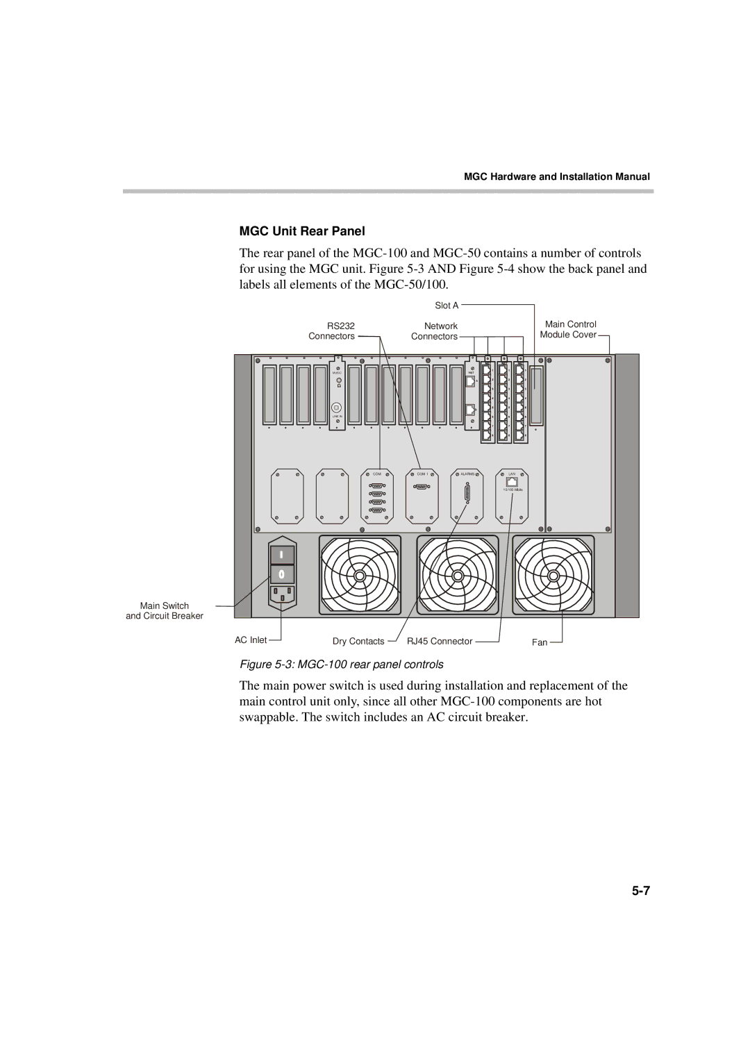
MGC Unit Rear Panel
The rear panel of the
Slot A
RS232 | Network |
| Main Control |
Connectors | Connectors |
| Module Cover |
MUSIC |
|
|
|
LINE IN |
|
|
|
COM | COM 1 | ALARMS | LAN |
|
|
| 10/100 Mbits |
AC Inlet | Dry Contacts | RJ45 Connector | Fan |
Figure 5-3: MGC-100 rear panel controls
The main power switch is used during installation and replacement of the main control unit only, since all other