MGC Hardware and Installation Manual
MPI-8 Network Interface Data Stream
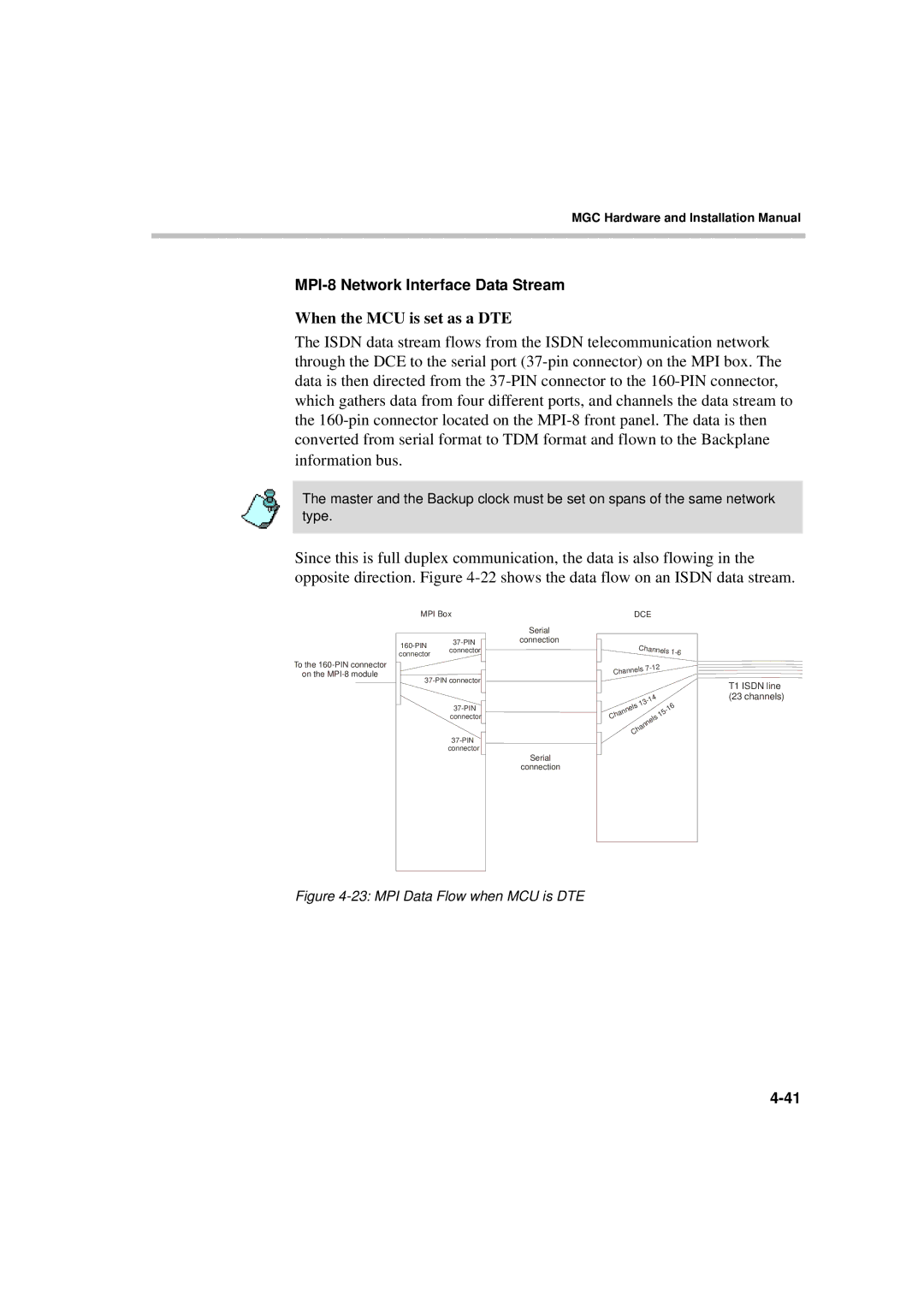
When the MCU is set as a DTE
The ISDN data stream flows from the ISDN telecommunication network through the DCE to the serial port
The master and the Backup clock must be set on spans of the same network type.
Since this is full duplex communication, the data is also flowing in the opposite direction. Figure
MPI Box |
|
|
|
|
|
| DCE |
| ||||
|
| Serial |
|
|
|
|
|
|
|
|
|
|
connection |
|
|
|
|
|
| Channels | |||||
connector |
|
|
|
|
|
|
| |||||
connector |
|
|
|
|
|
|
| |||||
|
|
|
|
|
|
|
|
|
|
|
| |
To the |
|
|
|
|
|
| nels | |||||
on the |
| Chan |
|
|
|
|
|
| ||||
|
|
|
|
|
|
|
|
|
|
| ||
|
|
|
|
|
|
|
|
|
|
| 4 |
|
|
|
|
|
|
|
|
|
|
|
| ||
|
|
|
|
|
|
|
|
| 3 |
|
| |
|
|
|
|
|
|
|
| 1 |
|
| 6 | |
|
|
| n |
| ls |
|
|
| ||||
|
|
| e |
|
|
|
| - | ||||
|
|
| a | n |
|
|
|
|
| 1 | ||
|
|
|
|
|
|
|
|
|
| 5 | ||
| connector | h |
|
|
|
|
|
|
| 1 | ||
| C |
|
|
|
|
|
|
|
| ls |
| |
|
|
|
|
|
|
|
|
|
| e |
| |
|
|
|
|
|
|
|
|
|
| n |
| |
|
|
|
|
|
|
|
|
| n |
|
| |
|
|
|
|
|
|
|
| a |
|
| ||
|
|
|
|
|
|
|
| h |
|
|
| |
|
|
|
|
|
| C |
|
|
|
| ||
Serial
connection
T1 ISDN line
(23 channels)