30 | Assembling and Maintaining AMT |
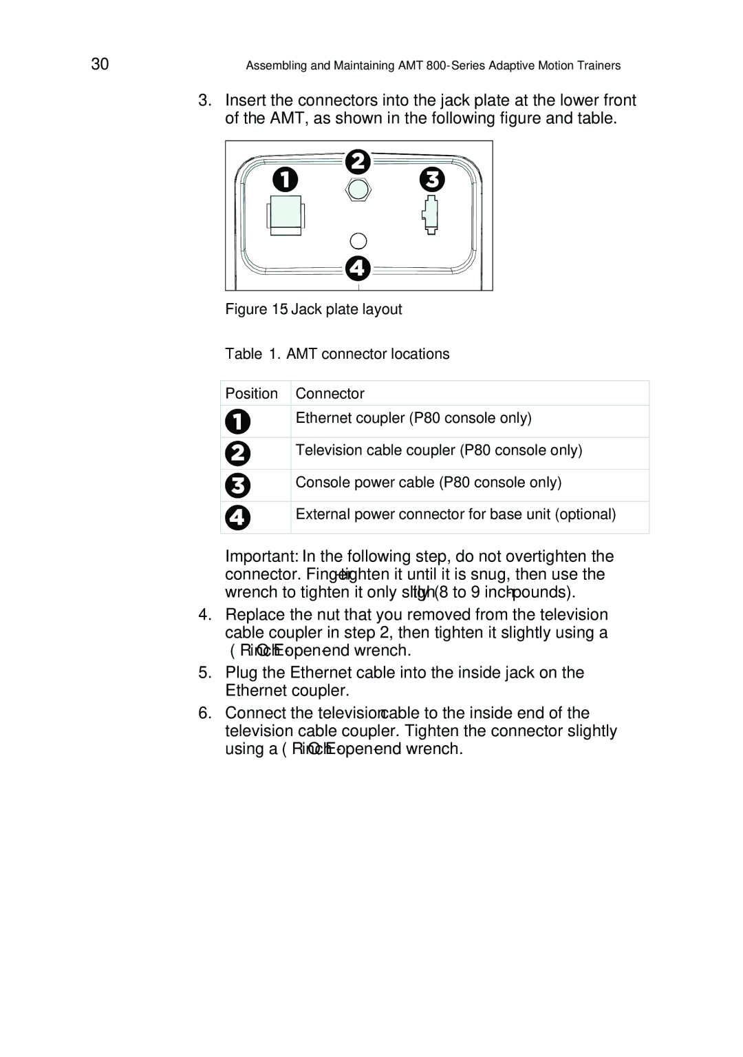
3.Insert the connectors into the jack plate at the lower front of the AMT, as shown in the following figure and table.
Figure 15: Jack plate layout
Table 1. AMT connector locations
Position Connector
Ethernet coupler (P80 console only)
Television cable coupler (P80 console only)
Console power cable (P80 console only)
External power connector for base unit (optional)
Important: In the following step, do not overtighten the connector.
4.Replace the nut that you removed from the television cable coupler in step 2, then tighten it slightly using a
5.Plug the Ethernet cable into the inside jack on the Ethernet coupler.
6.Connect the television cable to the inside end of the television cable coupler. Tighten the connector slightly using a