Hardware Setup
Case Connectors: F_P1 & F_P2
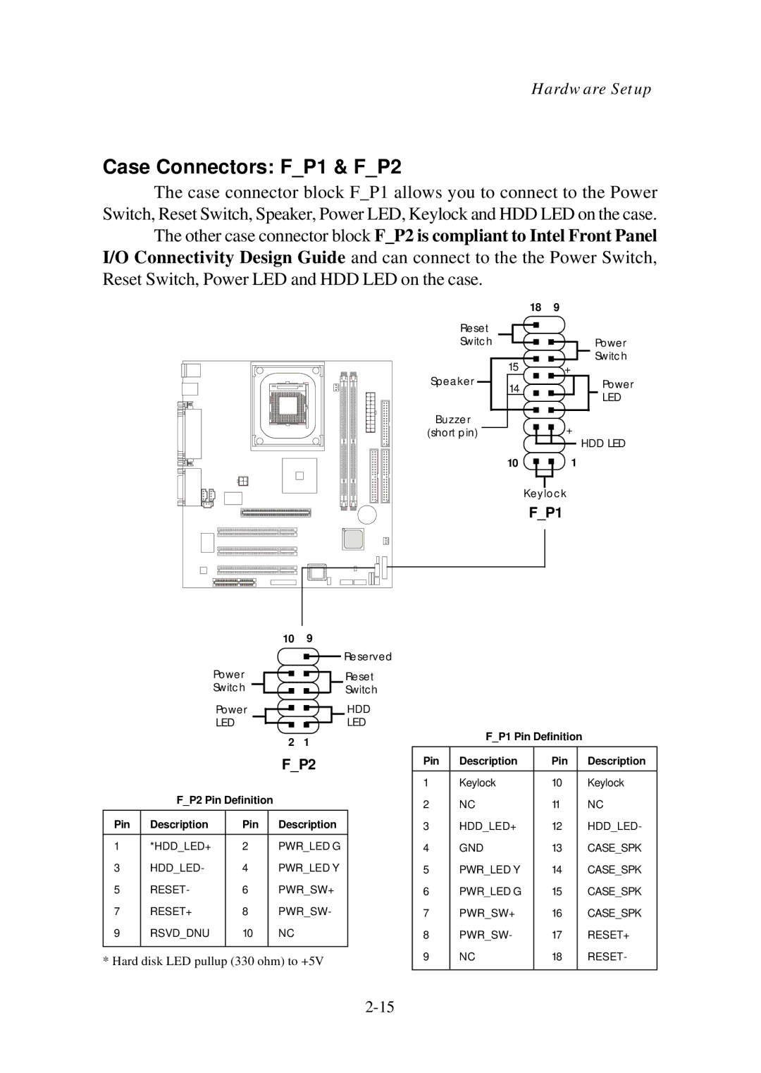
The case connector block F_P1 allows you to connect to the Power Switch, Reset Switch, Speaker, Power LED, Keylock and HDD LED on the case.
The other case connector block F_P2 is compliant to Intel Front Panel I/O Connectivity Design Guide and can connect to the the Power Switch, Reset Switch, Power LED and HDD LED on the case.
| 18 | 9 |
Reset |
|
|
Switch |
| Power |
| 15 | Switch |
Speaker | + | |
14 | Power | |
| LED | |
|
| |
Buzzer |
| + |
(short pin) |
| |
|
| HDD LED |
| 10 | 1 |
| Keylock | |
| F_P1 | |
|
|
|
|
|
|
|
|
|
| 10 | 9 |
|
|
|
|
|
|
|
|
| ||
|
| Power |
|
|
|
|
|
|
|
|
|
| Reserved |
|
|
|
| |||||
|
|
|
|
|
|
|
|
|
|
|
|
|
|
| ||||||||
|
|
|
|
|
|
|
|
|
|
| Reset |
|
|
|
| |||||||
|
| Switch |
|
|
|
|
|
|
|
|
|
| Switch |
|
|
|
| |||||
|
| Power |
|
|
|
|
|
|
|
|
| HDD |
|
|
|
| ||||||
|
| LED |
|
|
|
|
|
|
|
|
|
| LED | F_P1 Pin Definition |
| |||||||
|
|
|
|
|
| 2 | 1 |
|
|
| ||||||||||||
|
|
|
|
|
|
|
|
|
|
|
|
|
|
|
| |||||||
|
|
|
|
|
|
|
|
|
|
|
|
|
|
|
|
|
|
| ||||
|
|
|
|
|
|
|
|
|
| F_P2 |
|
|
| Pin | Description | Pin |
| Description | ||||
|
|
|
|
|
|
|
|
|
|
|
|
|
|
|
|
|
| 1 | Keylock | 10 |
| Keylock |
| F_P2 Pin Definition |
|
|
|
|
|
|
|
| 2 | NC | 11 |
| NC | ||||||||
Pin | Description |
| Pin |
| Description |
|
|
| 3 | HDD_LED+ | 12 |
| HDD_LED- | |||||||||
1 | *HDD_LED+ |
| 2 |
|
|
|
|
|
| PWR_LED G |
|
|
| 4 | GND | 13 |
| CASE_SPK | ||||
3 | HDD_LED- |
| 4 |
|
|
|
|
|
| PWR_LED Y |
|
| 5 | PWR_LED Y | 14 |
| CASE_SPK | |||||
5 | RESET- |
| 6 |
|
|
|
|
|
| PWR_SW+ |
|
| 6 | PWR_LED G | 15 |
| CASE_SPK | |||||
7 | RESET+ |
| 8 |
|
|
|
|
|
| PWR_SW- |
|
| 7 | PWR_SW+ | 16 |
| CASE_SPK | |||||
9 | RSVD_DNU |
| 10 |
|
|
|
| NC |
|
|
|
|
| 8 | PWR_SW- | 17 |
| RESET+ | ||||
|
|
|
|
|
| 9 | NC | 18 |
| RESET- | ||||||||||||
* Hard disk LED pullup (330 ohm) to +5V |
|
|
|
| ||||||||||||||||||