INSTALLATION
INSTALLATION
GAS PIPE PRESSURE
TESTING
The appliance must be isolated from the gas supply piping system by closing its individual manual
The manifold pressure is controlled by a regulator built into the gas control, and should be checked at the pressure test point.
Note: To properly check gas pressure, both inlet and manifold pressures should be checked using the valve pressure ports on the valve.
1)Make sure the valve is in the "OFF" position.
2)Loosen the "IN" and/or "OUT" pressure tap(s), turning counterclockwise with a 1/8" wide flat screwdriver.
3)Attach manometer to "IN" and/or "OUT" pressure tap(s) using a 5/16" ID hose.
4)Light the pilot and turn the valve to "ON" position.
5)The pressure check should be carried out with the unit burning and the setting should be within the limits specified on the safety label.
6)When finished reading manometer, turn off the gas valve, disconnect the hose and tighten the screw (clockwise) with a 1/8" flat screwdriver. Note: Screw should be snug, but do not over tighten.
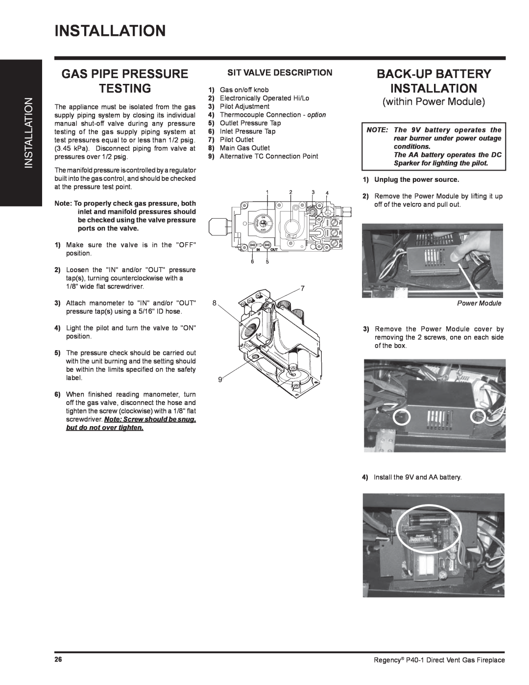
SIT VALVE DESCRIPTION
1) Gas on/off knob
2) Electronically Operated Hi/Lo
3) Pilot Adjustment
4) Thermocouple Connection - option
5) Outlet Pressure Tap
6) Inlet Pressure Tap
7) Pilot Outlet
8) Main Gas Outlet
9) Alternative TC Connection Point
1 | 2 | 3 | 4 |
IN | OUT |
|
|
6 5
BACK-UP BATTERY
INSTALLATION
(within Power Module)
NOTE: The 9V battery operates the rear burner under power outage conditions.
The AA battery operates the DC Sparker for lighting the pilot.
1)Unplug the power source.
2)Remove the Power Module by lifting it up off of the velcro and pull out.
Power Module
3)Remove the Power Module cover by removing the 2 screws, one on each side of the box.
4)Install the 9V and AA battery.
26 | Regency® |