DataNET Hub Specifications, Continued
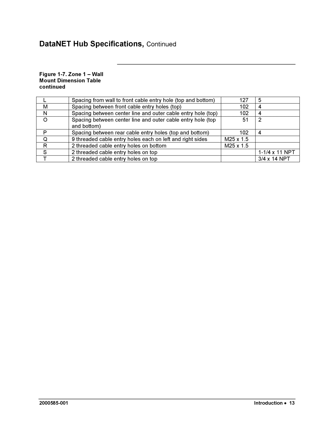
Figure 1-7. Zone 1 – Wall Mount Dimension Table continued
L | Spacing from wall to front cable entry hole (top and bottom) | 127 | 5 |
M | Spacing between front cable entry holes (top) | 102 | 4 |
N | Spacing between center line and outer cable entry hole (top) | 102 | 4 |
O | Spacing between center line and outer cable entry hole (top | 51 | 2 |
| and bottom) |
|
|
P | Spacing between rear cable entry holes (top and bottom) | 102 | 4 |
Q | 9 threaded cable entry holes each on left and right sides | M25 x 1.5 |
|
R | 2 threaded cable entry holes on bottom | M25 x 1.5 |
|
S | 2 threaded cable entry holes on top |
| |
T | 2 threaded cable entry holes on top |
| 3/4 x 14 NPT |
Introduction • 13 |