DataNET Copper Connections
Description
A & B Hubs
The DNH consist of two identical hubs in one enclosure. The left side is usually the DataNET ‘A’ Hub and the right side is the DataNET ‘B’ Hub. Each hub contains two DataNET Hub boards and power supplies. Figure
The DataNET ports can accept copper and/or fiber optic cables. In Data Hiway installations the DNH can use the existing Data Hiway cables.
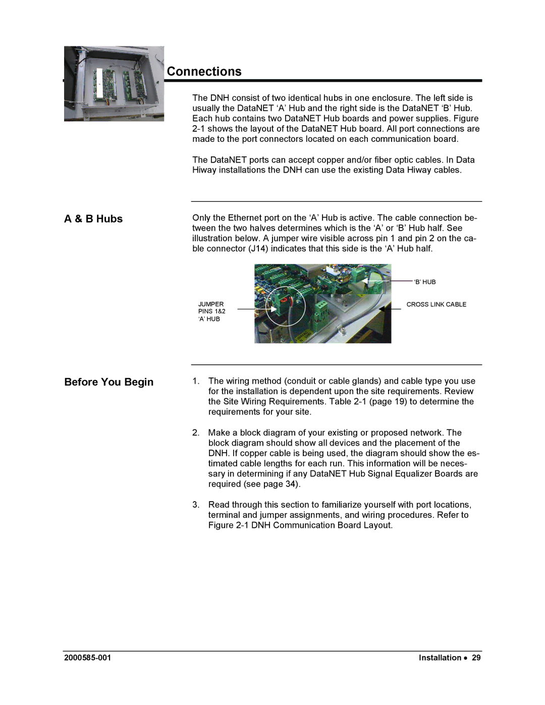
Only the Ethernet port on the ‘A’ Hub is active. The cable connection be- tween the two halves determines which is the ‘A’ or ‘B’ Hub half. See illustration below. A jumper wire visible across pin 1 and pin 2 on the ca- ble connector (J14) indicates that this side is the ‘A’ Hub half.
JUMPER |
|
|
| ‘B’ HUB | ||
|
|
| ||||
|
|
|
| |||
|
| CROSS LINK CABLE | ||||
PINS 1&2 |
|
|
|
|
|
|
|
|
|
|
| ||
‘A’ HUB |
|
|
|
| ||
|
|
|
| |||
Before You Begin
1.The wiring method (conduit or cable glands) and cable type you use for the installation is dependent upon the site requirements. Review the Site Wiring Requirements. Table
2.Make a block diagram of your existing or proposed network. The block diagram should show all devices and the placement of the DNH. If copper cable is being used, the diagram should show the es- timated cable lengths for each run. This information will be neces- sary in determining if any DataNET Hub Signal Equalizer Boards are required (see page 34).
3.Read through this section to familiarize yourself with port locations, terminal and jumper assignments, and wiring procedures. Refer to Figure
Installation • 29 |