Programming |
|
|
|
|
|
|
|
|
|
|
|
|
|
|
|
|
|
|
|
|
|
|
|
|
|
|
|
|
|
| Standard acquisition modes | |||||
|
|
|
|
|
|
|
|
|
|
|
|
|
|
|
|
|
|
|
|
|
|
|
|
|
|
|
|
| ||||||||
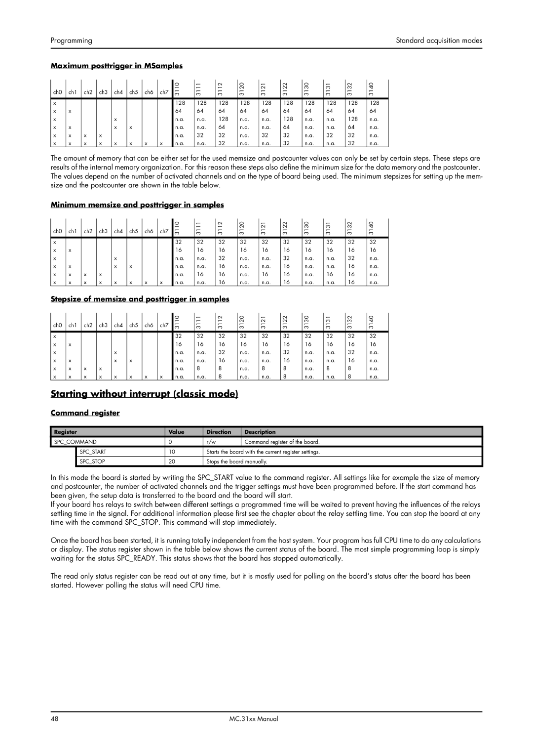
Maximum posttrigger in MSamples |
|
|
|
|
|
|
|
|
|
|
|
|
|
|
|
|
|
|
| |||||||||||||||||
| ch0 |
| ch1 |
| ch2 |
| ch3 |
| ch4 |
| ch5 |
| ch6 |
| ch7 |
| 3110 |
| 3111 |
| 3112 |
| 3120 |
| 3121 |
| 3122 |
| 3130 |
| 3131 |
| 3132 |
| 3140 |
|
|
|
|
|
|
|
|
|
|
|
|
|
|
|
|
|
|
|
| ||||||||||||||||||
|
|
|
|
|
|
|
|
|
|
|
|
|
|
|
|
|
|
|
|
|
|
|
|
|
|
|
|
|
|
|
|
|
|
|
|
|
| x |
|
|
|
|
|
|
|
|
|
|
|
|
|
|
| 128 |
| 128 |
| 128 |
| 128 |
| 128 |
| 128 |
| 128 |
| 128 |
| 128 |
| 128 |
|
| x |
| x |
|
|
|
|
|
|
|
|
|
|
|
|
| 64 |
| 64 |
| 64 |
| 64 |
| 64 |
| 64 |
| 64 |
| 64 |
| 64 |
| 64 |
|
| x |
|
|
|
|
|
|
| x |
|
|
|
|
|
|
| n.a. |
| n.a. |
| 128 |
| n.a. |
| n.a. |
| 128 |
| n.a. |
| n.a. |
| 128 |
| n.a. |
|
| x |
| x |
|
|
|
|
| x |
| x |
|
|
|
|
| n.a. |
| n.a. |
| 64 |
| n.a. |
| n.a. |
| 64 |
| n.a. |
| n.a. |
| 64 |
| n.a. |
|
| x |
| x |
| x |
| x |
|
|
|
|
|
|
|
|
| n.a. |
| 32 |
| 32 |
| n.a. |
| 32 |
| 32 |
| n.a. |
| 32 |
| 32 |
| n.a. |
|
| x |
| x |
| x |
| x |
| x |
| x |
| x |
| x |
| n.a. |
| n.a. |
| 32 |
| n.a. |
| n.a. |
| 32 |
| n.a. |
| n.a. |
| 32 |
| n.a. |
|
The amount of memory that can be either set for the used memsize and postcounter values can only be set by certain steps. These steps are results of the internal memory organization. For this reason these steps also define the minimum size for the data memory and the postcounter. The values depend on the number of activated channels and on the type of board being used. The minimum stepsizes for setting up the mem- size and the postcounter are shown in the table below.
Minimum memsize and posttrigger in samples
| ch0 |
| ch1 |
| ch2 |
| ch3 |
| ch4 |
| ch5 |
| ch6 |
| ch7 | 3110 | 3111 | 3112 | 3120 | 3121 | 3122 | 3130 | 3131 | 3132 | 3140 |
|
|
|
|
|
|
|
|
|
|
|
|
|
|
|
|
|
|
|
|
|
|
|
|
|
|
| x |
|
|
|
|
|
|
|
|
|
|
|
|
|
| 32 | 32 | 32 | 32 | 32 | 32 | 32 | 32 | 32 | 32 |
| x |
| x |
|
|
|
|
|
|
|
|
|
|
|
| 16 | 16 | 16 | 16 | 16 | 16 | 16 | 16 | 16 | 16 |
| x |
|
|
|
|
|
|
| x |
|
|
|
|
|
| n.a. | n.a. | 32 | n.a. | n.a. | 32 | n.a. | n.a. | 32 | n.a. |
| x |
| x |
|
|
|
|
| x |
| x |
|
|
|
| n.a. | n.a. | 16 | n.a. | n.a. | 16 | n.a. | n.a. | 16 | n.a. |
| x |
| x |
| x |
| x |
|
|
|
|
|
|
|
| n.a. | 16 | 16 | n.a. | 16 | 16 | n.a. | 16 | 16 | n.a. |
| x |
| x |
| x |
| x |
| x |
| x |
| x |
| x | n.a. | n.a. | 16 | n.a. | n.a. | 16 | n.a. | n.a. | 16 | n.a. |
Stepsize of memsize and posttrigger in samples |
|
|
|
|
|
|
| ||||||||||||||||||
| ch0 |
| ch1 |
| ch2 |
| ch3 |
| ch4 |
| ch5 |
| ch6 |
| ch7 |
|
|
|
|
|
|
|
|
|
|
|
|
|
|
|
|
|
| 3110 | 3111 | 3112 | 3120 | 3121 | 3122 | 3130 | 3131 | 3132 | 3140 | ||||||||
|
|
|
|
|
|
|
|
|
|
|
|
|
|
|
|
|
|
|
|
|
|
|
|
|
|
| x |
|
|
|
|
|
|
|
|
|
|
|
|
|
| 32 | 32 | 32 | 32 | 32 | 32 | 32 | 32 | 32 | 32 |
| x |
| x |
|
|
|
|
|
|
|
|
|
|
|
| 16 | 16 | 16 | 16 | 16 | 16 | 16 | 16 | 16 | 16 |
| x |
|
|
|
|
|
|
| x |
|
|
|
|
|
| n.a. | n.a. | 32 | n.a. | n.a. | 32 | n.a. | n.a. | 32 | n.a. |
| x |
| x |
|
|
|
|
| x |
| x |
|
|
|
| n.a. | n.a. | 16 | n.a. | n.a. | 16 | n.a. | n.a. | 16 | n.a. |
| x |
| x |
| x |
| x |
|
|
|
|
|
|
|
| n.a. | 8 | 8 | n.a. | 8 | 8 | n.a. | 8 | 8 | n.a. |
| x |
| x |
| x |
| x |
| x |
| x |
| x |
| x | n.a. | n.a. | 8 | n.a. | n.a. | 8 | n.a. | n.a. | 8 | n.a. |
Starting without interrupt (classic mode)
Command register
Register | Value | Direction | Description | |
SPC_COMMAND | 0 | r/w | Command register of the board. | |
| SPC_START | 10 | Starts the board with the current register settings. | |
|
|
|
| |
| SPC_STOP | 20 | Stops the board manually. | |
In this mode the board is started by writing the SPC_START value to the command register. All settings like for example the size of memory and postcounter, the number of activated channels and the trigger settings must have been programmed before. If the start command has been given, the setup data is transferred to the board and the board will start.
If your board has relays to switch between different settings a programmed time will be waited to prevent having the influences of the relays settling time in the signal. For additional information please first see the chapter about the relay settling time. You can stop the board at any time with the command SPC_STOP. This command will stop immediately.
Once the board has been started, it is running totally independent from the host system. Your program has full CPU time to do any calculations or display. The status register shown in the table below shows the current status of the board. The most simple programming loop is simply waiting for the status SPC_READY. This status shows that the board has stopped automatically.
The read only status register can be read out at any time, but it is mostly used for polling on the board’s status after the board has been started. However polling the status will need CPU time.
48 | MC.31xx Manual |