Analog Inputs | Setting up the inputs |
|
|
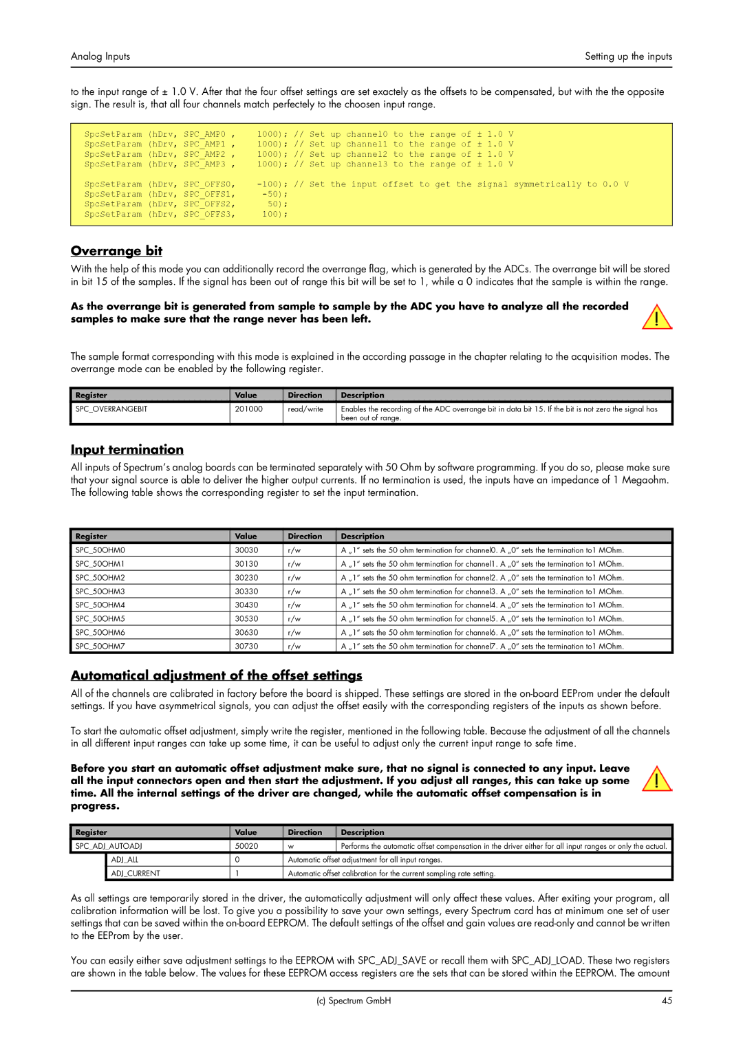
to the input range of ± 1.0 V. After that the four offset settings are set exactely as the offsets to be compensated, but with the the opposite sign. The result is, that all four channels match perfectely to the choosen input range.
SpcSetParam (hDrv, SPC_AMP0 , | 1000); // Set up channel0 to the range of | ± 1.0 | V |
SpcSetParam (hDrv, SPC_AMP1 , | 1000); // Set up channel1 to the range of | ± 1.0 | V |
SpcSetParam (hDrv, SPC_AMP2 , | 1000); // Set up channel2 to the range of | ± 1.0 | V |
SpcSetParam (hDrv, SPC_AMP3 , | 1000); // Set up channel3 to the range of | ± 1.0 | V |
SpcSetParam (hDrv, SPC_OFFS0, | signal symmetrically to 0.0 V | ||
SpcSetParam (hDrv, SPC_OFFS1, |
|
| |
SpcSetParam (hDrv, SPC_OFFS2, | 50); |
|
|
SpcSetParam (hDrv, SPC_OFFS3, | 100); |
|
|
Overrange bit
With the help of this mode you can additionally record the overrange flag, which is generated by the ADCs. The overrange bit will be stored in bit 15 of the samples. If the signal has been out of range this bit will be set to 1, while a 0 indicates that the sample is within the range.
As the overrange bit is generated from sample to sample by the ADC you have to analyze all the recorded samples to make sure that the range never has been left.
The sample format corresponding with this mode is explained in the according passage in the chapter relating to the acquisition modes. The overrange mode can be enabled by the following register.
Register | Value | Direction | Description |
SPC_OVERRANGEBIT | 201000 | read/write | Enables the recording of the ADC overrange bit in data bit 15. If the bit is not zero the signal has |
|
|
| been out of range. |
Input termination
All inputs of Spectrum’s analog boards can be terminated separately with 50 Ohm by software programming. If you do so, please make sure that your signal source is able to deliver the higher output currents. If no termination is used, the inputs have an impedance of 1 Megaohm. The following table shows the corresponding register to set the input termination.
Register | Value | Direction | Description |
SPC_50OHM0 | 30030 | r/w | A „1“ sets the 50 ohm termination for channel0. A „0“ sets the termination to1 MOhm. |
|
|
|
|
SPC_50OHM1 | 30130 | r/w | A „1“ sets the 50 ohm termination for channel1. A „0“ sets the termination to1 MOhm. |
SPC_50OHM2 | 30230 | r/w | A „1“ sets the 50 ohm termination for channel2. A „0“ sets the termination to1 MOhm. |
SPC_50OHM3 | 30330 | r/w | A „1“ sets the 50 ohm termination for channel3. A „0“ sets the termination to1 MOhm. |
|
|
|
|
SPC_50OHM4 | 30430 | r/w | A „1“ sets the 50 ohm termination for channel4. A „0“ sets the termination to1 MOhm. |
SPC_50OHM5 | 30530 | r/w | A „1“ sets the 50 ohm termination for channel5. A „0“ sets the termination to1 MOhm. |
SPC_50OHM6 | 30630 | r/w | A „1“ sets the 50 ohm termination for channel6. A „0“ sets the termination to1 MOhm. |
|
|
|
|
SPC_50OHM7 | 30730 | r/w | A „1“ sets the 50 ohm termination for channel7. A „0“ sets the termination to1 MOhm. |
Automatical adjustment of the offset settings
All of the channels are calibrated in factory before the board is shipped. These settings are stored in the
To start the automatic offset adjustment, simply write the register, mentioned in the following table. Because the adjustment of all the channels in all different input ranges can take up some time, it can be useful to adjust only the current input range to safe time.
Before you start an automatic offset adjustment make sure, that no signal is connected to any input. Leave all the input connectors open and then start the adjustment. If you adjust all ranges, this can take up some time. All the internal settings of the driver are changed, while the automatic offset compensation is in progress.
Register | Value | Direction | Description | |
SPC_ADJ_AUTOADJ | 50020 | w | Performs the automatic offset compensation in the driver either for all input ranges or only the actual. | |
| ADJ_ALL | 0 | Automatic offset adjustment for all input ranges. | |
| ADJ_CURRENT | 1 | Automatic offset calibration for the current sampling rate setting. | |
As all settings are temporarily stored in the driver, the automatically adjustment will only affect these values. After exiting your program, all calibration information will be lost. To give you a possibility to save your own settings, every Spectrum card has at minimum one set of user settings that can be saved within the
You can easily either save adjustment settings to the EEPROM with SPC_ADJ_SAVE or recall them with SPC_ADJ_LOAD. These two registers are shown in the table below. The values for these EEPROM access registers are the sets that can be stored within the EEPROM. The amount
(c) Spectrum GmbH | 45 |