Standard acquisition modes | Programming |
|
|
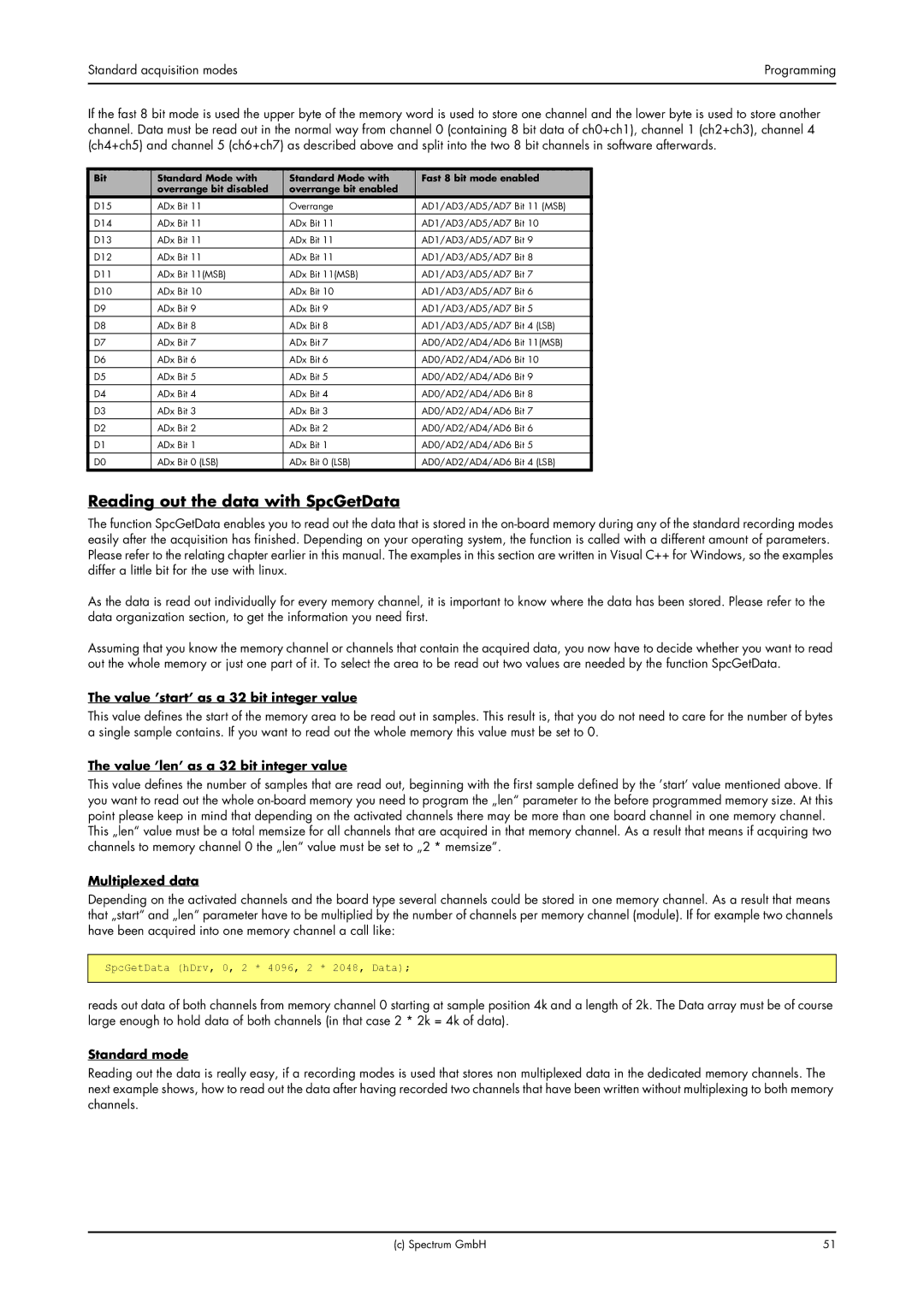
If the fast 8 bit mode is used the upper byte of the memory word is used to store one channel and the lower byte is used to store another channel. Data must be read out in the normal way from channel 0 (containing 8 bit data of ch0+ch1), channel 1 (ch2+ch3), channel 4 (ch4+ch5) and channel 5 (ch6+ch7) as described above and split into the two 8 bit channels in software afterwards.
Bit | Standard Mode with | Standard Mode with | Fast 8 bit mode enabled |
| overrange bit disabled | overrange bit enabled |
|
D15 | ADx Bit 11 | Overrange | AD1/AD3/AD5/AD7 Bit 11 (MSB) |
|
|
|
|
D14 | ADx Bit 11 | ADx Bit 11 | AD1/AD3/AD5/AD7 Bit 10 |
|
|
|
|
D13 | ADx Bit 11 | ADx Bit 11 | AD1/AD3/AD5/AD7 Bit 9 |
D12 | ADx Bit 11 | ADx Bit 11 | AD1/AD3/AD5/AD7 Bit 8 |
|
|
|
|
D11 | ADx Bit 11(MSB) | ADx Bit 11(MSB) | AD1/AD3/AD5/AD7 Bit 7 |
|
|
|
|
D10 | ADx Bit 10 | ADx Bit 10 | AD1/AD3/AD5/AD7 Bit 6 |
D9 | ADx Bit 9 | ADx Bit 9 | AD1/AD3/AD5/AD7 Bit 5 |
|
|
|
|
D8 | ADx Bit 8 | ADx Bit 8 | AD1/AD3/AD5/AD7 Bit 4 (LSB) |
|
|
|
|
D7 | ADx Bit 7 | ADx Bit 7 | AD0/AD2/AD4/AD6 Bit 11(MSB) |
D6 | ADx Bit 6 | ADx Bit 6 | AD0/AD2/AD4/AD6 Bit 10 |
|
|
|
|
D5 | ADx Bit 5 | ADx Bit 5 | AD0/AD2/AD4/AD6 Bit 9 |
|
|
|
|
D4 | ADx Bit 4 | ADx Bit 4 | AD0/AD2/AD4/AD6 Bit 8 |
D3 | ADx Bit 3 | ADx Bit 3 | AD0/AD2/AD4/AD6 Bit 7 |
|
|
|
|
D2 | ADx Bit 2 | ADx Bit 2 | AD0/AD2/AD4/AD6 Bit 6 |
|
|
|
|
D1 | ADx Bit 1 | ADx Bit 1 | AD0/AD2/AD4/AD6 Bit 5 |
D0 | ADx Bit 0 (LSB) | ADx Bit 0 (LSB) | AD0/AD2/AD4/AD6 Bit 4 (LSB) |
Reading out the data with SpcGetData
The function SpcGetData enables you to read out the data that is stored in the
As the data is read out individually for every memory channel, it is important to know where the data has been stored. Please refer to the data organization section, to get the information you need first.
Assuming that you know the memory channel or channels that contain the acquired data, you now have to decide whether you want to read out the whole memory or just one part of it. To select the area to be read out two values are needed by the function SpcGetData.
The value ’start’ as a 32 bit integer value
This value defines the start of the memory area to be read out in samples. This result is, that you do not need to care for the number of bytes a single sample contains. If you want to read out the whole memory this value must be set to 0.
The value ’len’ as a 32 bit integer value
This value defines the number of samples that are read out, beginning with the first sample defined by the ’start’ value mentioned above. If you want to read out the whole
This „len“ value must be a total memsize for all channels that are acquired in that memory channel. As a result that means if acquiring two channels to memory channel 0 the „len“ value must be set to „2 * memsize“.
Multiplexed data
Depending on the activated channels and the board type several channels could be stored in one memory channel. As a result that means that „start“ and „len“ parameter have to be multiplied by the number of channels per memory channel (module). If for example two channels have been acquired into one memory channel a call like:
SpcGetData (hDrv, 0, 2 * 4096, 2 * 2048, Data);
reads out data of both channels from memory channel 0 starting at sample position 4k and a length of 2k. The Data array must be of course large enough to hold data of both channels (in that case 2 * 2k = 4k of data).
Standard mode
Reading out the data is really easy, if a recording modes is used that stores non multiplexed data in the dedicated memory channels. The next example shows, how to read out the data after having recorded two channels that have been written without multiplexing to both memory channels.
(c) Spectrum GmbH | 51 |
