Synchronization (Option) | Setup synchronization for use with FIFO mode and equally clokked boards |
|
|
All clock rates of all synchronized boards are derived from the clock signal that is distributed via the sync bus. This clock is the sum samplerate of one module of the clock master board. Based on this speed the clock rates of the slave boards can be set. As these clock rates are divided from the sync clock, the board with the maximum sum sample rate should be set up as clock master.
Calculating the clock dividers
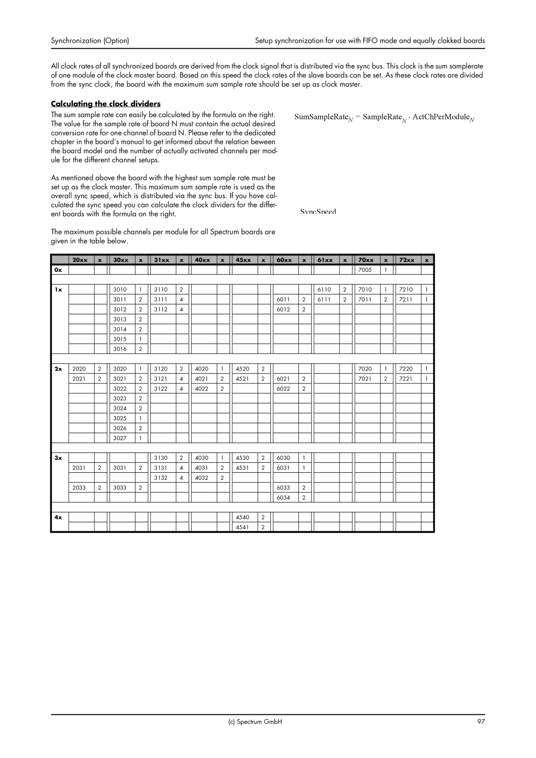
The sum sample rate can easily be calculated by the formula on the right. The value for the sample rate of board N must contain the actual desired conversion rate for one channel of board N. Please refer to the dedicated chapter in the board’s manual to get informed about the relation beween the board model and the number of actually activated channels per mod- ule for the different channel setups.
As mentioned above the board with the highest sum sample rate must be set up as the clock master. This maximum sum sample rate is used as the overall sync speed, which is distributed via the sync bus. If you have cal- culated the sync speed you can calculate the clock dividers for the differ- ent boards with the formula on the right.
The maximum possible channels per module for all Spectrum boards are given in the table below.
SumSampleRateN = SampleRateN ⋅ ActChPerModuleN
SyncSpeed
| 20xx | x | 30xx | x | 31xx | x | 40xx | x | 45xx | x | 60xx | x | 61xx | x | 70xx | x | 72xx | x |
0x |
|
|
|
|
|
|
|
|
|
|
|
|
|
| 7005 | 1 |
|
|
|
|
|
|
|
|
|
|
|
|
|
|
|
|
|
|
|
|
|
|
|
|
|
|
|
|
|
|
|
|
|
|
|
|
|
|
|
|
1x |
|
| 3010 | 1 | 3110 | 2 |
|
|
|
|
|
| 6110 | 2 | 7010 | 1 | 7210 | 1 |
|
|
|
|
|
|
|
|
|
|
|
|
|
|
|
|
|
|
|
|
|
| 3011 | 2 | 3111 | 4 |
|
|
|
| 6011 | 2 | 6111 | 2 | 7011 | 2 | 7211 | 1 |
|
|
|
|
|
|
|
|
|
|
|
|
|
|
|
|
|
|
|
|
|
| 3012 | 2 | 3112 | 4 |
|
|
|
| 6012 | 2 |
|
|
|
|
|
|
|
|
| 3013 | 2 |
|
|
|
|
|
|
|
|
|
|
|
|
|
|
|
|
|
|
|
|
|
|
|
|
|
|
|
|
|
|
|
|
|
|
|
| 3014 | 2 |
|
|
|
|
|
|
|
|
|
|
|
|
|
|
|
|
|
|
|
|
|
|
|
|
|
|
|
|
|
|
|
|
|
|
|
| 3015 | 1 |
|
|
|
|
|
|
|
|
|
|
|
|
|
|
|
|
| 3016 | 2 |
|
|
|
|
|
|
|
|
|
|
|
|
|
|
|
|
|
|
|
|
|
|
|
|
|
|
|
|
|
|
|
|
|
|
|
|
|
|
|
|
|
|
|
|
|
|
|
|
|
|
|
|
2x | 2020 | 2 | 3020 | 1 | 3120 | 2 | 4020 | 1 | 4520 | 2 |
|
|
|
| 7020 | 1 | 7220 | 1 |
| 2021 | 2 | 3021 | 2 | 3121 | 4 | 4021 | 2 | 4521 | 2 | 6021 | 2 |
|
| 7021 | 2 | 7221 | 1 |
|
|
| 3022 | 2 | 3122 | 4 | 4022 | 2 |
|
| 6022 | 2 |
|
|
|
|
|
|
|
|
|
|
|
|
|
|
|
|
|
|
|
|
|
|
|
|
|
|
|
| 3023 | 2 |
|
|
|
|
|
|
|
|
|
|
|
|
|
|
|
|
| 3024 | 2 |
|
|
|
|
|
|
|
|
|
|
|
|
|
|
|
|
| 3025 | 1 |
|
|
|
|
|
|
|
|
|
|
|
|
|
|
|
|
|
|
|
|
|
|
|
|
|
|
|
|
|
|
|
|
|
|
|
| 3026 | 2 |
|
|
|
|
|
|
|
|
|
|
|
|
|
|
|
|
| 3027 | 1 |
|
|
|
|
|
|
|
|
|
|
|
|
|
|
|
|
|
|
|
|
|
|
|
|
|
|
|
|
|
|
|
|
|
3x |
|
|
|
| 3130 | 2 | 4030 | 1 | 4530 | 2 | 6030 | 1 |
|
|
|
|
|
|
| 2031 | 2 | 3031 | 2 | 3131 | 4 | 4031 | 2 | 4531 | 2 | 6031 | 1 |
|
|
|
|
|
|
|
|
|
|
| 3132 | 4 | 4032 | 2 |
|
|
|
|
|
|
|
|
|
|
|
|
|
|
|
|
|
|
|
|
|
|
|
|
|
|
|
|
|
| 2033 | 2 | 3033 | 2 |
|
|
|
|
|
| 6033 | 2 |
|
|
|
|
|
|
|
|
|
|
|
|
|
|
|
|
| 6034 | 2 |
|
|
|
|
|
|
|
|
|
|
|
|
|
|
|
|
|
|
|
|
|
|
|
|
|
4x |
|
|
|
|
|
|
|
| 4540 | 2 |
|
|
|
|
|
|
|
|
|
|
|
|
|
|
|
|
| 4541 | 2 |
|
|
|
|
|
|
|
|
(c) Spectrum GmbH | 97 |