Channel Trigger | Trigger modes and appendant registers |
|
|
Channel Trigger
Overview of the channel trigger registers
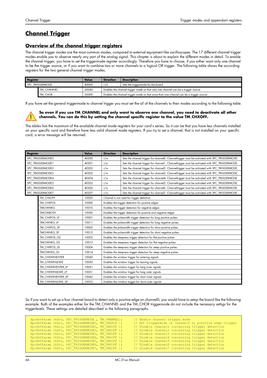
The channel trigger modes are the most common modes, compared to external equipment like oscilloscopes. The 17 different channel trigger modes enable you to observe nearly any part of the analog signal. This chapter is about to explain the different modes in detail. To enable the channel trigger, you have to set the triggermode register accordingly. Therefore you have to choose, if you either want only one channel to be the trigger source, or if you want to combine two or more channels to a logical OR trigger. The following table shows the according registers for the two general channel trigger modes.
Register | Value | Direction | Description | |
SPC_TRIGGERMODE | 40000 | r/w | Sets the triggermode for the board. | |
| TM_CHANNEL | 20040 | Enables the channel trigger mode so that only one channel can be a trigger source. | |
| TM_CHOR | 35000 | Enables the channel trigger mode so that more than one channel can be a trigger source. | |
If you have set the general triggermode to channel trigger you must set the all of the channels to their modes according to the following table.
So even if you use TM_CHANNEL and only want to observe one channel, you need to deactivate all other channels. You can do this by setting the channel specific register to the value TM_CHXOFF.
The tables lists the maximum of the available channel mode registers for your card’s series. So it can be that you have less channels installed on your specific card and therefore have less valid channel mode registers. If you try to set a channel, that is not installed on your specific card, a error message will be returned.
Register | Value | Direction | Description | |
SPC_TRIGGERMODE0 | 40200 | r/w | Sets the channel trigger for channel0. Channeltrigger must be activated with SPC_TRIGGERMODE. | |
SPC_TRIGGERMODE1 | 40201 | r/w | Sets the channel trigger for channel1. Channeltrigger must be activated with SPC_TRIGGERMODE. | |
|
|
|
|
|
SPC_TRIGGERMODE2 | 40202 | r/w | Sets the channel trigger for channel2. Channeltrigger must be activated with SPC_TRIGGERMODE. | |
|
|
|
|
|
SPC_TRIGGERMODE3 | 40203 | r/w | Sets the channel trigger for channel3. Channeltrigger must be activated with SPC_TRIGGERMODE. | |
SPC_TRIGGERMODE4 | 40204 | r/w | Sets the channel trigger for channel4. Channeltrigger must be activated with SPC_TRIGGERMODE. | |
SPC_TRIGGERMODE5 | 40205 | r/w | Sets the channel trigger for channel5. Channeltrigger must be activated with SPC_TRIGGERMODE. | |
|
|
|
|
|
SPC_TRIGGERMODE6 | 40206 | r/w | Sets the channel trigger for channel6. Channeltrigger must be activated with SPC_TRIGGERMODE. | |
SPC_TRIGGERMODE7 | 40207 | r/w | Sets the channel trigger for channel7. Channeltrigger must be activated with SPC_TRIGGERMODE. | |
| TM_CHXOFF | 10020 | Channel is not used for trigger detection. | |
|
|
|
| |
| TM_CHXPOS | 10000 | Enables the trigger detection for positive edges | |
| TMCHXNEG | 10010 | Enables the trigger detection for negative edges | |
| TMCHXBOTH | 10030 | Enables the trigger detection for positive and negative edges | |
|
|
|
| |
| TM_CHXPOS_LP | 10001 | Enables the pulsewidth trigger detection for long positive pulses | |
| TMCHXNEG_LP | 10011 | Enables the pulsewidth trigger detection for long negative pulses | |
| TM_CHXPOS_SP | 10002 | Enables the pulsewidth trigger detection for short positive pulses | |
|
|
|
| |
| TMCHXNEG_SP | 10012 | Enables the pulsewidth trigger detection for short negative pulses | |
| TM_CHXPOS_GS | 10003 | Enables the steepness trigger detection for flat positive pulses | |
| TMCHXNEG_GS | 10013 | Enables the steepness trigger detection for flat negative pulses | |
|
|
|
| |
| TM_CHXPOS_SS | 10004 | Enables the steepness trigger detection for steep positive pulses | |
| TMCHXNEG_SS | 10014 | Enables the steepness trigger detection for steep negative pulses | |
| TM_CHXWINENTER | 10040 | Enables the window trigger for entering signals | |
|
|
|
| |
| TM_CHXWINLEAVE | 10050 | Enables the window trigger for leaving signals | |
| TM_CHXWINENTER_LP | 10041 | Enables the window trigger for long inner signals | |
| TM_CHXWINLEAVE_LP | 10051 | Enables the window trigger for long outer signals | |
|
|
|
| |
| TM_CHXWINENTER_SP | 10042 | Enables the window trigger for short inner signals | |
| TM_CHXWINLEAVE_SP | 10052 | Enables the window trigger for short outer signals | |
So if you want to set up a four channel board to detect only a positive edge on channel0, you would have to setup the board like the following example. Both of the examples either for the TM_CHANNEL and the TM_CHOR triggermode do not include the necessary settigs for the triggerlevels. These settings are detailed described in the following paragraphs.
SpcSetParam (hDrv, | SPC_TRIGGERMODE , | TM_CHANNEL); | // Enable channel trigger mode |
SpcSetParam (hDrv, SPC_TRIGGERMODE0, TM_CHXPOS ); | // Set triggermode of channel0 to positive edge trigger | ||
SpcSetParam (hDrv, SPC_TRIGGERMODE1, | TM_CHXOFF ); | // Disable channel1 concerning trigger detection | |
SpcSetParam (hDrv, SPC_TRIGGERMODE2, | TM_CHXOFF ); | // Disable channel2 concerning trigger detection | |
SpcSetParam (hDrv, SPC_TRIGGERMODE3, | TM_CHXOFF ); | // Disable channel3 concerning trigger detection | |
SpcSetParam (hDrv, SPC_TRIGGERMODE4, | TM_CHXOFF ); | // Disable channel4 concerning trigger detection | |
SpcSetParam (hDrv, SPC_TRIGGERMODE5, | TM_CHXOFF ); | // Disable channel5 concerning trigger detection | |
SpcSetParam (hDrv, SPC_TRIGGERMODE6, | TM_CHXOFF ); | // Disable channel6 concerning trigger detection | |
SpcSetParam (hDrv, SPC_TRIGGERMODE7, | TM_CHXOFF ); | // Disable channel7 concerning trigger detection | |
|
|
|
|
66 | MC.31xx Manual |