Manuals
/
Spectrum Brands
/
Computer Equipment
/
Computer Hardware
Spectrum Brands
MC.31XX
manual
MC.3112 MC.3122 MC.3132, Different models of the MC.31xx series
Models:
MC.31XX
1
8
102
102
Download
102 pages
5.49 Kb
5
6
7
8
9
10
11
12
Install
Error codes
Block diagram Technical Data
Error handling
Resulting start delays
Mounting the wired boards
Powerdown and reset
Setting up the inputs
Command register
Driver Update
Page 8
Image 8
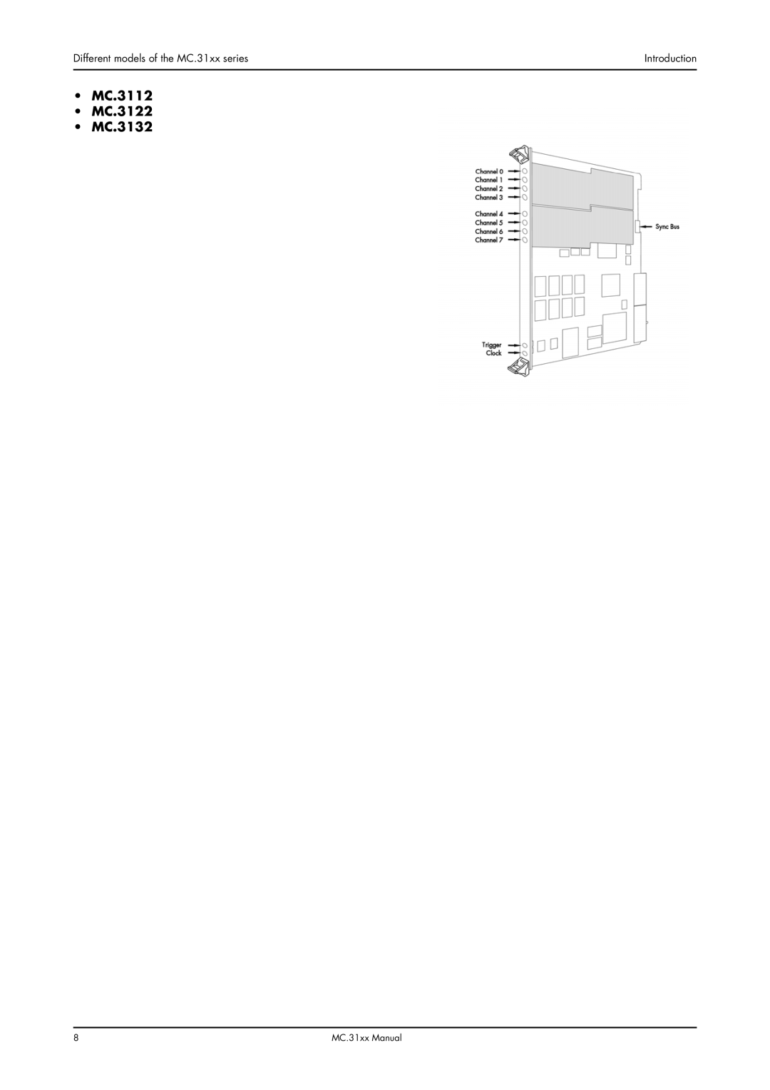
Different models of the MC.31xx series
Introduction
•
MC.3112
•
MC.3122
•
MC.3132
8
MC.31xx Manual
Page 7
Page 9
Page 8
Image 8
Page 7
Page 9
Contents
MC.31xx
English version April 27
Page
Hardware Installation
Software Driver Installation
Introduction
Software
Fifo Mode
Programming the Board
Analog Inputs
Standard acquisition modes
Option Multiple Recording
Option Gated Sampling
Option Timestamp
Option Extra I/O
Introduction
Preface
General Information
Preface
Introduction
Different models of the MC.31xx series
MC.3110 MC.3120 MC.3130 MC.3111 MC.3121 MC.3131
MC.3112 MC.3122 MC.3132
Additional options
Digital inputs
Extra I/O Option -XMF
Introduction Additional options
Starhub
Timestamp
Spectrum type plate
Block diagram Technical Data
Hardware information
Dynamic Parameters
Order information
IntroductionHardware information
Order No Description
System Requirements
Hardware Installation
Installing the board in the system
Hardware Installation
Installing a board with digital inputs/outputs
Installing a board with extra I/O Option -XMF
Installing multiple boards synchronized by starhub
Mounting the wired boards
Hooking up the boards
Only use the included flat ribbon cables
Installing multiple synchronized boards
Interrupt Sharing
Software Driver Installation
Interrupt Sharing
Installation
Software Driver Installation Windows
Windows
Version control
Driver Update
Windows
Driver Update
Software Driver Installation
Windows XP
Windows XP
Adding boards to the Windows NT driver
Software Driver Installation Windows NT
Windows NT
Linux
Overview
Installing the device
Now it is possible to access the board using this device
Driver info
Automatic load of the driver
Software
Software Overview
First Test with SBench
Software Overview
++ Driver Interface
Header files
Microsoft Visual C++
Borland C++ Builder
Other Windows C/C++ compilers
National Instruments LabWindows/CVI
Driver functions
Include Drivers
Software ++ Driver Interface Using the Driver under Linux
Function SpcSetParam
Function SpcSetParam
Function SpcSetData Windows
Delphi Pascal Programming Interface
Type definition
Include Driver
Examples
Software
VBA for Excel Examples
Visual Basic Programming Interface
Visual Basic Examples
Visual Basic Programming Interface
Error handling
Programming the Board
Overview
Register tables
Example for error checking
Initialization
Starting the automatic initialization routine
PCI Register
Installed memory
Installed features and options
Hardware version
Date of production
Used interrupt line
Used type of driver
Programming the Board Initialization
Driver version
Powerdown and reset
Example program for the board initialization
Spcpcimemsize
Spcpciserialno
Analog Inputs
Channel Selection
Important note on channels selection
Analog Inputs
Channel rerouting
Rerouting information for module
SPCCHROUTE0
SPCCHROUTE1
Setting up the inputs
Input ranges
Input offset
Register Value Direction Description Offset range
Input termination
Automatical adjustment of the offset settings
Overrange bit
Spcadjautoadj Adjall
Spcadjsave ADJUSER0
Standard acquisition modes
Programming
Memory, Pre- and Posttrigger
Pretrigger = memsize posttrigger
Starting without interrupt classic mode
Command register
Maximum posttrigger in MSamples
Minimum memsize and posttrigger in samples
Status register
Starting with interrupt driven mode
Standard acquisition modes Programming
Normal mode
Fast 8 bit mode
201100 Enables the fast 8 bit mode
Data organization
Standard mode
Reading out the data with SpcGetData
Value ’start’ as a 32 bit integer value
Value ’len’ as a 32 bit integer value
Programming
Fifo Mode
General Information
Background Fifo Read
Speed Limitations
Programming Fifo Mode
Software Buffers
Theoretical maximum sample rate PCI Bus Throughput
60040 Read out the number of available Fifo buffers
Fifo Mode Programming
Buffer processing
Analog acquisition or generation boards
Digital I/O 701x or 702x or pattern generator boards
Example Fifo acquisition mode
Fifo acquisition example
Spcfifostart
Spcfifowait
Sample format
Standard internal sample rate
Clock generation
Internally generated sample rate
Using plain quartz without PLL
Maximum internal sample rate in MS/s normal mode
External reference clock
Clock generation
External clocking
Direct external clock
Minimum external sample rate
Maximum external samplerate in MS/s
Fifo
External clock with divider
CHANNEL0 CHANNEL1 CHANNEL2 CHANNEL3
Trigger modes and appendant registers
General Description
Software trigger
External TTL trigger
Example on how to set up the board for positive TTL trigger
Edge triggers
Trigger modes and appendant registers
Positive TTL trigger
Pulsewidth triggers
Positive and negative TTL trigger
TTL pulsewidth trigger for long High pulses
TTL pulsewidth trigger for short High pulses
TTL pulsewidth trigger for long LOW pulses
TTL pulsewidth trigger for short LOW pulses
Spctriggermode Tmttlhighlp
Spcpulsewidth
Channel Trigger
Overview of the channel trigger registers
Spctriggermode Tmchannel
Tmchxoff
Triggerlevel
Spctriggermode Tmchor
SPCTRIGGERMODE0 Tmchxoff
SPCTRIGGERMODE2 Tmchxoff
Reading out the number of possible trigger levels
SPCTRIGGERMODE0 Tmchxpos
SPCHIGHLEVEL0
Input ranges Triggerlevel ±50 mV ±100 mV ±200 mV ±500 mV
Detailed description of the channel trigger modes
Channel trigger on positive edge
Channel trigger on negative edge
Channel trigger on positive and negative edge
Channel pulsewidth trigger for long positive pulses
Channel pulsewidth trigger for long negative pulses
Tmchxposgsp
Channel pulsewidth trigger for short positive pulses
Channel pulsewidth trigger for short negative pulses
Channel steepness trigger for flat positive pulses
Channel steepness trigger for flat negative pulses
Channel steepness trigger for steep positive pulses
Channel steepness trigger for steep negative pulses
Channel window trigger for entering signals
Channel window trigger for leaving signals
Channel window trigger for long inner signals
Channel window trigger for long outer signals
Channel window trigger for short inner signals
Channel window trigger for short outer signals
Standard Mode
When using Multiple Recording pretrigger is not available
Option Multiple Recording
Recording modes
Resulting start delays
Trigger modesOption Multiple Recording
Spcmemsize
Spctriggermode
General information and trigger delay
Option Gated Sampling
Option Gated Sampling
Spcgate
End of gate alignement
Alignement samples per channel
Number of samples on gate signal
Allowed trigger modes
Option Gated SamplingTrigger modes
External TTL edge trigger
Example program
Example program Option Gated Sampling
Channel trigger
Spctriggermode Tmttlpos
StartReset mode
Option Timestamp
Timestamp modes
Limits
RefClock mode optional
Functions for accessing the data
Timestamp Status
Reading out timestamp data
Spctimestampcount
Data format
SpcGetData nr, ch, start, len, data
Acquisition with Multiple Recording
Standard acquisition mode
Example programs
Option Extra I/O
Digital I/Os
Analog Outputs
Channel direction
Programming example
Programming example Option Extra I/O
Bit Standard Mode Digital Inputs enabled
Option Digital inputs
Sample format
Spcreaddigital
Synchronization Option
Different synchronization options
Synchronization with option cascading
Synchronization with option starhub
Setup order for the different synchronization options
Set up the board parameters
Let the master calculate it’s clocking
Write Data to on-board memory output boards only
Example for data writing
Define the boards for trigger master
Example of board #2 set as trigger master
4a Define synchronization or trigger
Define the board for clock master
Example board number 0 is clock master
Define the remaining boards as clock slaves
Arm the boards for synchronization
Start all of the trigger master boards
Wait for the end of the measurement
Read data from the on-board memory acquisition boards only
Restarting the board for another synchronized run
Example of Fifo buffer allocation
2a Write first data for output boards
Spcsyncmasterfifo
Spcsyncslavefifo
Additions for synchronizing different boards
General information
Calculating the clock dividers
20xx 30xx 31xx 40xx 45xx 60xx 61xx 70xx 72xx
Setting up the clock divider
Board type 3122 3120
40 MS/s
Board type 3025 3131
Resulting delays using different boards or speeds
Delay in standard non Fifo modes
Delay in Fifo mode
Additions for equal boards with different sample rates
Error Codes
Error Codes
Error name Value hex Value dec Error description
Appendix
Option Digital inputs
Pin assignment of the multipin connector
Extra I/O with external connectorOption -XMF
Pin assignment of the multipin cable
Top
Page
Image
Contents