Programming | Standard acquisition modes |
|
|
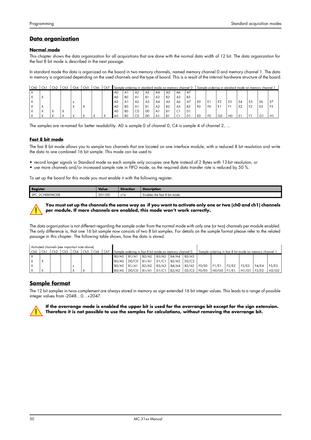
Data organization
Normal mode
This chapter shows the data organization for all acquisitions that are done with the normal data width of 12 bit. The data organization for the fast 8 bit mode is described in the next passage.
In standard mode tha data is organized on the board in two memory channels, named memory channel 0 and memory channel 1. The data in memory is organized depending on the used channels and the type of board. This is a result of the internal hardware structure of the board.
Ch0 | Ch1 | Ch2 | Ch3 | Ch4 | Ch5 | Ch6 | Ch7 | Sample ordering in standard mode on memory channel 0 | Sample ordering in standard mode on memory channel 1 | ||||||||||||||
X |
|
|
|
|
|
|
| A0 | A1 | A2 | A3 | A4 | A5 | A6 | A7 |
|
|
|
|
|
|
|
|
X | X |
|
|
|
|
|
| A0 | B0 | A1 | B1 | A2 | B2 | A3 | B3 |
|
|
|
|
|
|
|
|
X |
|
|
| x |
|
|
| A0 | A1 | A2 | A3 | A4 | A5 | A6 | A7 | E0 | E1 | E2 | E3 | E4 | E5 | E6 | E7 |
X | X |
|
| X | X |
|
| A0 | B0 | A1 | B1 | A2 | B2 | A3 | B3 | E0 | F0 | E1 | F1 | E2 | F2 | E3 | F3 |
X | X | X | X |
|
|
|
| A0 | B0 | C0 | D0 | A1 | B1 | C1 | D1 |
|
|
|
|
|
|
|
|
X | X | X | X | X | X | X | X | A0 | B0 | C0 | D0 | A1 | B1 | C1 | D1 | E0 | F0 | G0 | H0 | E1 | F1 | G1 | H1 |
The samples are
Fast 8 bit mode
The fast 8 bit mode allows you to sample two channels that are located on one interface module, with a reduced 8 bit resolution and write the data to one combined 16 bit sample. This mode can be used to
•record longer signals in Standard mode as each sample only occupies one Byte instead of 2 Bytes with
•use more channels and/or increased sample rate in FIFO mode, as the required data transfer rate is reduced by 50 %.
To set up the board for this mode you must enable it with the following register.
Register | Value | Direction | Description |
SPC_2CH8BITMODE | 201100 | r/w | Enables the fast 8 bit mode. |
You must set up the channels the same way as if you want to activate only one or two (ch0 and ch1) channels per module. If more channels are enabled, this mode won’t work correctly.
The data organization is not different regarding the sample order from the normal mode with only one (or two) channels per module enabled. The only difference is, that one 16 bit sample now consists of two 8 bit samples. For details on the sample format please refer to the related passage in this chapter. The following table shows, how the data is stored.
Activated channels (see important note above) |
|
|
|
|
|
|
|
|
|
|
|
|
| ||||||
Ch0 | Ch1 | Ch2 | Ch3 | Ch4 | Ch5 | Ch6 | Ch7 | Sample ordering in fast 8 bit mode on memory channel 0 | Sample ordering in fast 8 bit mode on memory channel 1 | ||||||||||
X |
|
|
|
|
|
|
| B0/A0 | B1/A1 | B2/A2 | B3/A3 | B4/A4 | B5/A5 |
|
|
|
|
|
|
X | X |
|
|
|
|
|
| B0/A0 | D0/C0 | B1/A1 | D1/C1 | B2/A2 | D2/C2 |
|
|
|
|
|
|
X |
|
|
| x |
|
|
| B0/A0 | B1/A1 | B2/A2 | B3/A3 | B4/A4 | B5/A5 | F0/E0 | F1/E1 | F2/E2 | F3/E3 | F4/E4 | F5/E5 |
X | X |
|
| X | X |
|
| B0/A0 | D0/C0 | B1/A1 | D1/C1 | B2/A2 | D2/C2 | F0/E0 | H0/G0 | F1/E1 | H1/G1 | F2/E2 | H2/G2 |
Sample format
The 12 bit samples in twos complement are always stored in memory as sign extended 16 bit integer values. This leads to a range of possible integer values from
If the overrange mode is enabled the upper bit is used for the overrange bit except for the sign extension. Therefore it is not possible to use the samples for calculations, without removing the overrange bit.
50 | MC.31xx Manual |