lever
-
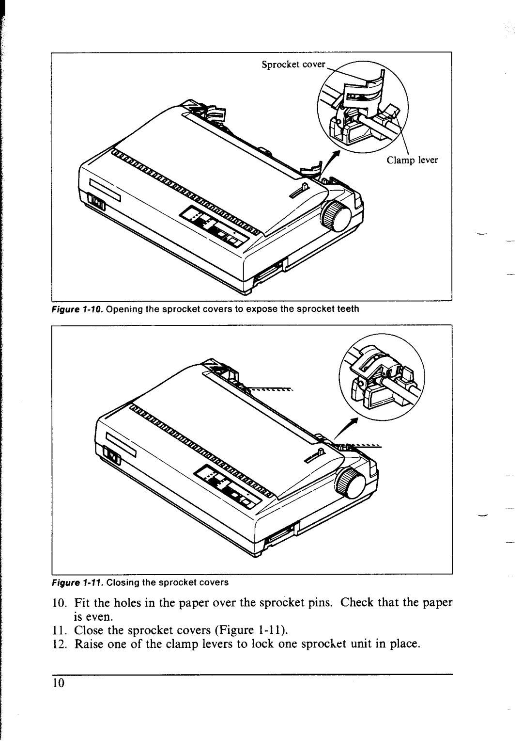
Figure l-10. Opening the sprocket covers to expose the sprocket teeth
igure l-71. Closing the sprocket covers
10.Fit the holes in the paper over the sprocket pins. Check that the paper is even.
11.Close the sprocket covers (Figure
12.Raise one of the clamp levers to lock one sprocket unit in place.