AIR-CONDITIONER
Contents
10-2
10-1
10-3
10-4
Explanation of illustrated marks
Explanation of indications
Confirmation of warning label on the main unit
Indication Explanation
Never recover the refrigerant into the outdoor unit
∗ For details, refer to the parts list
Do not modify the products
For spare parts, use those specified ∗
Metal section Earth position
Check the following items after reinstallation
Side
Limit even if the refrigerant leaks
Pipe Materials
Safety Caution Concerned to New Refrigerant
Copper pipe Piping
Flare nut
Used tool Usage
General tools Conventional tools can be used
R410A Conventional air
Digital Inverter
Indoor Unit
Way Air Discharge Cassette Type
SP562AT-E SP802AT-E
Super Digital Inverter
RAV SM562BT-E SM802BT-E
Concealed Duct Type
Super Digital Inverter
RAV SM562CT-E SM802CT-E
Under Ceiling Type
Super Digital Inverter
Indoor unit
Twin Type
16.7/14.6
RAV SM562AT-E SM802AT-E
SP562AT-E SP802AT-E
RAV-SM562AT-E, RAV-SM802AT-E
Operation characteristic curve Digital Inverter
Cooling Heating
Current
RAV-SP1102AT-E
Operation characteristic curve Super Digital Inverter
Outdoor temp. ˚C
Capacity variation ratio according to temperature
Ratio Capacity
Tap
Pressure
High
Low Static
Tap Low
Static Pressure Tap
RAV-SM562UT-E, RAV-SM802UT-E
188
RAV-SM1102UT-E, RAV-SM1402UT-E, RAV-SP1102UT-E
Suction port canvas Separate sold
Dimension
RAV-SM562CT-E, RAV-SM802CT-E, RAV-SM1102CT-E, RAV-SM1402CT-E
Space required for service
365
RAV-SP1102AT-E, RAV-SP1402AT-E
RAV-SM562UT-E, RAV-SM562BT-E, RAV-SM562CT-E / RAV-SM562AT-E
Outdoor unit
Indoor Outdoor
RAV-SM802UT-E, RAV-SM802BT-E, RAV-SM802CT-E / RAV-SM802AT-E
Outer dia. Ø B
50m
Outer dia. B
To sensor SKV-18D26 TD sensor
RAV-SM562UT-E, RAV-SM562BT-E, RAV-SM562CT-E / RAV-SP562AT-E
Outer dia. ØB TS sensor Strainer Modulating
RAV-SM802UT-E, RAV-SM802BT-E, RAV-SM802CT-E / RAV-SP802AT-E
Refrigerant pipe At gas side Outer dia. Ø a Ball valve
TCJ sensor Distributor
Indoor unit
LM2 3
LM1 3
Color
Identification
Color
Indoor Unit
LM 3
Identification
MCC-5009
Board
SM562AT-E, RAV-SM802AT-E
Color Identification
GRY Gray YEL Yellow
MCC-1438
Board
MCC-1531
SUB P.C. board
RAV-SP562AT-E, RAV-SP802AT-E
SUB P.C. board
RAV-SP1102UT-E
Parts name Type Specifications
RAV-SM1102UT-E, RAV-SM1402UT-E
MP24GA1
RAV-SM1102AT-E
RAV-SM562AT-E
RAV-SM802AT-E
RAV-SM1402AT-E
RBC-U21PG W E2 Ceiling panel
TCB-DP22CE2 Drain up kit
TCB-DP11E2 Drain up pump
RAV-SM560AT-E, RAV-SM560UT-E, RAV-SM560BT-E
Piping Materials and Joints Used
Safety During Installation/Servicing
1 Thicknesses of annealed copper pipes Thickness mm
Processing of Piping Materials
Outer diameter mm R410A R22
12.7 15.9
R410A clutch type Clutch type Wing nut type
Flare tool for Conventional flare tool
R22 clutch type Clutch type Wing nut type
Diameter Width mm
13.0 13.5 12.7 16.2 16.0 12.9 15.9 19.4 19.0 23.3 24.0 19.2
43˚to 45˚
Nm kgfm
Wrenches available on the market
Refer to the 4. Tools
Required Tools
Flux
Materials for Brazing
Brazing
Characteristics required for flux
Types of flux
Piping materials for brazing and used brazing filler/flux
Indoor unit
Main Sub master remote controller
Indoor Control Circuit
Outline of specifications Remarks
Cool
Setting at shipment
Heating Auto
Operation
Heat
Tcj Zone
Control temp C
All modes
Arning
Cooling/dry operation In heating/fan operation
Frequency fixed In case of wired remote controller
Operation Prohibited
Last push priority
Center
Remarks
Outline of specifications
Normal control
Circuit Board
Indoor Print
Ay Air
Concealed Duct Type / Under Ceiling Type
Pulse Motor Valve P.M.V. control
Discharge temperature release control
Current release control
For the cooling only models
Outdoor Controls
Indoor P.C. Board Optional Connector Specifications
Print Circuit Board
Board Comparison Table for Digital Inverter
RAV -SM562AT-E
MCC-5009
SM802AT-E Board
Iewed fromparts
SP802AT-E
MCC-1531
RAV -SM1102AT
SM1402AT-E / RAV
MCC-1531
RAV -SP562AT-E, RAV RAV -SM1102AT-E, RAV
Ipdu MCC-1438
SM1402AT-E
SP1402AT-E
Pulse Modulating V alve PMV control
Outline of Main Controls
Outdoor fan control
Operation with WE
Allocations of fan tap revolutions rpm
TE ˚C TD ˚C
Trouble of TE sensor
Coil heating control
To ˚C
TE ˚C
Start of heating operation
Defrost control
TE ºC
Zone
Troubleshooting procedure
Summary of Troubleshooting
Ired remote controller type Before troubleshooting
Trouble Confirmation of lamp display
Error mode detected by indoor and outdoor units
Check Code List
Cause of operation Status of air Condition
Error mode detected by central remote controller
Error mode detected by remote controller
SW801 LED display in bit 1, bit 2 OFF
Error Mode Detected by LED on Outdoor P.C. Board
Check code
¡ Go on l Go off ¥ Flash 5Hz
E01 error
Troubleshooting Procedure for Each Check Code
E09 error
Check Code
E04 error
E18 error
E10 error
E08, L03, L07, L08 error
L09 error
L30 error
L20 error
P10 error
F10 error
CN334
P12 error Only for 4-way air discharge cassette type models
CN333
P22 error
F02 error
P19 error
P26 error
F01 error
H03 error
P29 error
F08 error
F06 error
F04 error
H02 error
L29 error
H01 error
P03 error
P04 error
Same as others Correct connection of connector
C06 error Central controller
P31 error Sub indoor unit
E03 error Master indoor unit
F29 error / 12 error
TA sensor TC, TCJ sensor Caracteristics-2 Caracteristics-1
100
Caracteristics-3
20 TE, TO, TS sensor
101
Replacement Procedure
H2 Replacement of service P.C. board
H1 Readout of the setup data from Eeprom
Contents
102
R3 Writing of the setup contents to Eeprom
104
Memorandum for setup contents Item code table Example
Type Item code
Indoor unit capacity Item code
Wired remote controller
Test Run Setup on Remote Controller
105
RAV-SM562UT-E, RAV-SM802UT-E, RAV-SM562BT-E, RAV-SM802BT-E
106
Use either Cool or Heat operation mode for test operation
107
Case of wireless remote controller
Item No. DN table Selection of function
108
Indoor unit is controlled by 2 remote controllers
Cabling and Setting of Remote Controller Control
Setup method
109
110
Monitor Function of Remote Controller Switch
111
Group control operation
112
Setup at Local Site / Oth ers
TCC-LINK Adapter For TCC-LINK Central Control
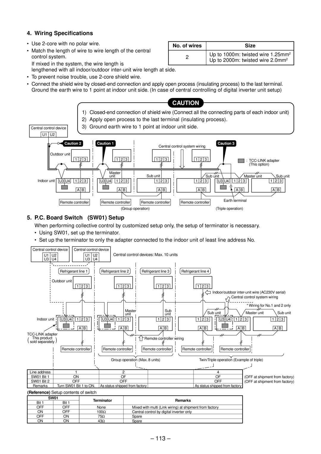
C. Board Switch SW01 Setup
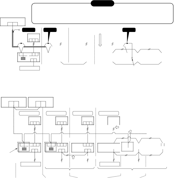
Wiring Specifications
113
Size
114
How to set up central control address number
Address setup procedure
Address Setup
Item code Data at sh ipment Setup data range
115
Sy stem configuration
Address Setup & Group Control
Only turning on source power supply Automatic completion
Automatic address example from unset address No miscabling
117
Manual setting from remote controller
END
Procedure
Procedure Push On / OFF button if th e unit stops
118
To k now th e position of indoor unit body by address
119
No. Part name Procedure Remarks
Detachment
Attachment
120
121
122
CN102 TCJ sensor 2P Red CN333 Power supply of fan motor
† Fan motor 1. Detachment
Remove nuts fixing the fan motor to Remove it
‡ Drain pan 1. Detachment
123
Body 1 position, and then remove Assembly. Ø4 × 8, 3 pcs
Assembly Perform works of items 1 of , 1 of ‚
Fix the drain pump assembly as before
124
Heat
Part name Procedure Remarks
125
RAV-SM562UT-E
Replacement of Distributor Assembly
126
RAV-SM802UT-E
127
128
129
130
131
132
Motor Remove the connector of the fan
„ Multi blade fan Remove the suction grille
Case side. Then fans come off
133
Heat exchanger support
134
135
136
Procedure Remarks
137
138
Take off fixed screw for the valve mounting
139
By hands so that the fan motor does not
Fall Tighten the flange nut with torque 4.9Nm 50kgf/cm
140
Fan guard
141
Perform works of items 1 of , and ‚
With minus screwdriver along with
Remove the upper cabinet. ST1T Ø4 × 10L, 6 pcs
142
Clamp
Fin guard Heat exchanger ST1T Ø4 × 10, 2 pcs
143
Discharge port cabinet for the heat
144
Remove the connectors by releasing lock
Relay connector
145
Terminal block 5P, Black
146
Remove the connectors by releasing lock Housing
Rectifier diode
Bottom
Loosen the flange nut by turning clock
147
Motor and the propeller fan
148
149
Product
150
151
‚ Air-outlet cabinet
152
Put the upper left side of the air-outlet
Cabinet on the end plate of heat ex
CN702 PMV Pulse Motor Valve coil
153
„ Inverter Perform the works in 1 of and ƒ
154
Remove connectors and lead wires
155
Case of RAV-SP1402AT-E
156
Case of RAV-SP1102AT-E
‰ PMV coil
157
Pay attention that 4-way valve or PMV is
158
Reactor Perform works of items to „
159
Electric parts box as shown below so that
They do not come to contact with the reac Tor
225
209 230 232
208
202
161
402 404 401 405 403
209
211 230 232 225
224
212 208 205 216, 218
163
224 201 212 208 204 216, 218 223 213, 214 228 207
211 229 231
164
232 43166006 Remotr Controller
165
RBC-U21PG W E2
304 311 306 305 301 307 302 303 310 313 308 309
166
RAV-SM562BT-E
902 36, 37, 38
43180311 Air Filter 43166002 Remotr Controller
43166004 Remotr Controller SX-A11JE2 RBC-AS21E2 43166005
43196012 Bushing 43166002 Remotr Controller
904 901, 902, 903 32, 33, 34
RAV-SM802BT-E
RAV-SM1102BT-E, RAV-SM1402BT-E
904 901, 902 34, 35, 36
170
402 404 403 406 405401407
22, 23
44, 45
36, 37, 38,39, 54
33, 34, 35,53, 56
172
404 43158193 Reactor
404401 407 403 406 402 405
173
RAVSM562AT-E RAV-SM802AT-E
174
175
705 701 702 708 707 706 710
RAV-SM1102AT-E, RAV-SM1402AT-E
176
177
707 708 706 704 703 701 705 702 710
43146695 Valve, Pulse, Modulating
21,22 16,17
178
179
704 707
180
Inverter 26,27 23,24 28,29
181
710 706 704
709
Drain up Kit
Replacement of Main Parts Sold Separately
182
TCB-DP22CE2
RBC-AX22CE2
Wireless Remote Control Kit
183
184
Required parts for installation work Recommendation
Part name ’ty Specifications/Vendor Remarks
185
Required tools for installation work
Part name Specifications Usage
186
Cord heater installation wiring diagram
187
Cord heater installation work procedure
Photo / Explanatory diagram Procedure
Assembly and the sound insulation board
Remove the motor base assembly, partition plate
188
Remove the fixing screws of the heat exchanger
189
190
191
Photo / Explanatory diagram Procedure Assembly
Material SGCC-Z08, Thickness 0.8t
Drawing of thermostat fixing plate
192
Ø3.4 burring hole Upward Ø3.4 burring hole Downward
Appendix
RAV-SP562AT-E, RAV-SP802AT-E, RAV-SP1102AT-E, RAV-SP1402AT-E
Check of Concentration Limit
Toshiba Carrier Corporation