<SUPER DIGITAL INVERTER>
INDOOR UNIT
OUTDOOR UNIT
<DIGITAL INVERTER>
WIRING DIAGRAM
CONTENTS
SAFETY CAUTION
SPECIFICATIONS
7. REFRIGERANT R410A
8. CONTROL BLOCK DIAGRAM
– 4 –
SAFETY CAUTION
DANGER
DANGER
– 5 –
– 6 –
2Joint
• New Refrigerant R410A
1 Copper pipe <Piping>
<Flare nut>
4.Tools
General tools Conventional tools can be used
– 8 –
– 9 –
1. SPECIFICATIONS
1-1.Indoor Unit
1-1-1. 4-WayAir Discharge Cassette Type
<Super Digital Inverter>
– 10 –
– 11 –
1-1-2.Concealed Duct Type
– 12 –
– 13 –
1-1-3.Under Ceiling Type
– 14 –
Outdoor unit
1-1-4.Twin Type
– 15 –
Indoor unit
– 16 –
– 17 –
1-2.Outdoor Unit
– 18 –
RAV-SM802AT-E
– 19 –
<Cooling>
<Heating>
<Heating>
– 20 –
RAV-SP562AT-E, RAV-SP802AT-E
<Cooling>
– 21 –
<Cooling>
<Heating>
– 22 –
2. AIR DUCTING WORK
Fig. 6 RAV-SM1102BT-ESquare duct
– 23 –
Fig. 5 RAV-SM1102BT-ERound duct
Fig. 7 RAV-SM1402BT-ERound duct
– 24 –
3. CONSTRUCTION VIEWS EXTERNAL VIEWS
3-1.Indoor Unit
3-1-1. 4-WayAir Discharge Cassette Type
RAV-SM1102UT-E, RAV-SM1402UT-E, RAV-SP1102UT-E
– 25 –
• Dimension
3-1-2.Concealed Duct Type
– 26 –
– 27 –
3-1-3.Under Ceiling Type
Space required for service
3-2.Outdoor Unit
– 28 –
– 29 –
RAV-SP1102AT-E, RAV-SP1402AT-E
– 30 –
Outdoor unit
4. SYSTEMATIC REFRIGERATING CYCLE DIAGRAM
Revised : Nov.
Indoor unit
– 32 –
Revised : Nov.
Indoor unit
Outdoor unit
Indoor unit
Outdoor unit
– 33 –
Indoor unit
Outdoor unit
– 34 –
– 35 –
Revised : Nov.
Indoor unit
Outdoor unit
– 36 –
Revised : Nov.
Indoor unit
Outdoor unit
Indoor unit
– 37 –
Outdoor unit
Indoor unit
– 38 –
Outdoor unit
Indoor Unit
5. WIRING DIAGRAM
MCC-1402
Control P.C. Board for
5-1-2.Concealed Duct Type
MCC-1402
Control P.C. Board for
Indoor Unit
5-1-3.Under Ceiling Type
MCC-1402
Control P.C. Board for
Indoor Unit
MCC-5009
1 2 3 L N
Outdoor Unit Wiring Diagram
P.C. Board
Color Identification
SUB P.C. board
MCC-1438
MCC-1531
P.C. board
MCC-1531
MCC-1438
P.C. board
SUB P.C. board
– 46 –
6. SPECIFICATIONS OF ELECTRICAL PARTS
6-1.Indoor Unit
6-1-1. 4-WayAir Discharge Cassette Type
6-1-2.Concealed Duct Type
6-1-3.Under Ceiling Type
– 47 –
– 48 –
6-2.Outdoor Unit
RAV-SP1102AT-E, RAV-SP1402AT-E
– 49 –
RAV-SM1402AT-E
RAV-SP562AT-E, RAV-SP802AT-E
– 50 –
6-3.Accessory Separate Soldparts
7-2-1.Piping Materials and Joints Used
7-1.Safety During Installation/Servicing
7-2.Refrigerant Piping Installation
7. REFRIGERANT R410A
Thickness mm
7-2-2.Processing of Piping Materials
– 52 –
Table 7-2-1Thicknesses of annealed copper pipes
Outer
Fig. 7-2-1Flare processing dimensions
Dimension mm
– 53 –
Nominal
Table 7-2-6Flare and flare nut dimensions for R22
Dimension mm
– 54 –
7-3-1.Required Tools
Fig. 7-4-1Configuration of refrigerant charging
7-3.Tools
7-4.Recharging of Refrigerant
– 56 –
7-5.Brazing of Pipes
7-5-1.Materials for Brazing
7-5-2.Flux
•Activated flux
7-5-3.Brazing
– 57 –
•Noncorrosive flux
8. CONTROL BLOCK DIAGRAM
8-1.Indoor Control Circuit
– 58 –
Item
8-2.Control Specifications
Outline of specifications
– 59 –
Item
Outline of specifications
– 60 –
<COOL>
Item
Outline of specifications
– 61 –
<HEAT>
Remarks
Outline of specifications
– 62 –
Item
Remarks
Outline of specifications
– 63 –
Item
Remarks
Outline of specifications
– 64 –
Item
Option for 4-wayair discharge cassette type only
<In case of wireless remote controller>
Outline of specifications
– 65 –
Remarks
Outline of specifications
– 66 –
Item
Item
Outline of specifications
Revised : Nov.
– 67 –
– 68 –
8-3.Indoor Print
Circuit Board
8-3-1. 4-Way Air
For the cooling only models
REQUIREMENT
Revised : Nov.
– 69 –
9-2.Outdoor Controls
9-2-1.Print Circuit Board
– 70 –
SM802AT-E
– 71 –
<MCC-5009>
RAV -SM562AT-E
SM1402AT-E /RAV
– 72 –
RAV -SM1102AT
E, RAV
– 73 –
E, RAV
<MCC-1531>
RAV -SM1102AT-E,RAV
– 74 –
<IPDU : MCC-1438>
RAV -SP562AT-E,RAV
REQUIREMENT
9-2-2.Outline of Main Controls
– 75 –
Operation with WE
– 76 –
Allocations of fan tap revolutions rpm
Object: SM562, SM802
– 77 –
5.Coil heating control
In trouble of TE sensor
– 78 –
6. Defrost control
Start of heating operation
Confirmation of check code display →
10. TROUBLESHOOTING
– 79 –
Trouble
Trouble
1.Before troubleshooting
2.Troubleshooting procedure
– 80 –
Page
Judgment and measures
Diagnostic function
Timer
¥: Flash, ¡: Go on, l: Go off
– 83 –
Error mode detected by remote controller
Error mode detected by central remote controller
Revised : Nov.
– 84 –
– 85 –
10-4-1.Check Code
– 86 –
E04 error
L09 error
E10 error
E18 error
E08, L03, L07, L08 error
F10 error
L20 error
L30 error
P10 error
– 89 –
P12 error
– 90 –
CN301, *CN303 CN300
P19 error
F02 error
– 91 –
F01 error
P26 error
– 92 –
P29 error
H03 error
– 93 –
– 94 –
F06 error
F04 error
F08 error
L29 error
H02 error
– 95 –
P03 error
H01 error
– 96 –
– 97 –
P04 error
– 98 –
C06 error Central controller
– 99 –
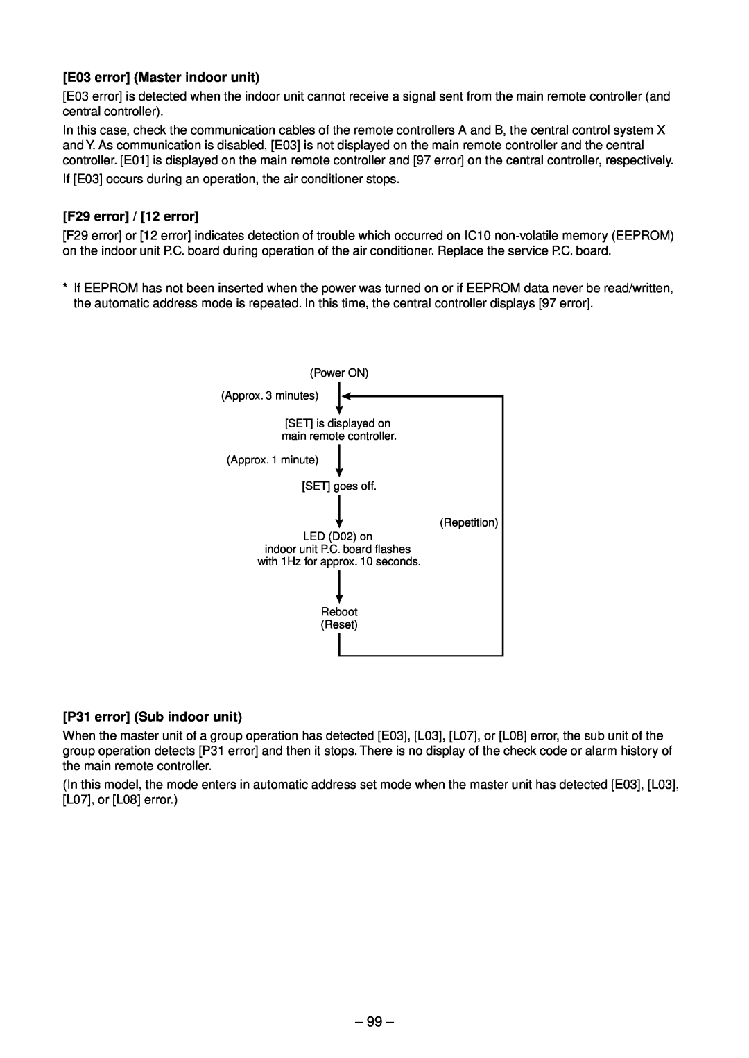
E03 error Master indoor unit
F29 error / 12 error
P31 error Sub indoor unit
30Caracteristics-2 Caracteristics-1
100
TA sensor
TC, TCJ sensor
– 101 –
11. REPLACEMENT OF SERVICE INDOOR P.C. BOARD
CASE
CASE
Minimum requirements for item code
H1 Readout of the setup data from EEPROM
H2 Replacement of service P.C. board
– 102 –
3 4 6
r3 Writing of the setup contents to EEPROM
– 103 –
– 104 –
Type Item code
Indoor unit capacity Item code
12-1.Indoor Unit
12. SETUP AT LOCAL SITE AND OTHERS
3 4 5
12-1-1.Test Run Setup on Remote Controller
– 106 –
– 107 –
4, 5,
Item No. DN table Selection of function
– 108 –
– 109 –
2 Push th e temperature setup
2 4 1
<Contents>
<Procedure>
– 111 –
Group control operation
– 112 –
12-2.Setup at Local Site / Oth ers
Size
4. Wiring Specifications
5.P.C. Board Switch SW01 Setup
– 113 –
2 1 5
12-3.How to set up central control address number
– 114 –
13. ADDRESS SETUP
13-1.Address Setup
– 115 –
13-2-1.Sy stem configuration
13-2.Address Setup & Group Control
1 2 3 4 5 6 7 8 9 10 11 END
10 11
2, 5,
3, 6, 9 4, 7,
1 2 END
1 2 3 END
– 118 –
– 119 –
14. DETACHMENTS
Procedure
14-1-1. 4-WayAir Discharge Cassette Type
2.Attachment
Procedure
120
1. Detachment
Remarks
Procedure
– 121 –
No. Part name
2.Attachment
Procedure
– 122 –
†Fan motor 1. Detachment
2.Attachment
Procedure
– 123 –
‡Drain pan 1. Detachment
3. Attachment
Procedure
– 124 –
ˆDrain pump 1. Detachment
Remarks
Procedure
– 125 –
Part name
No. of capillary tubes
<Replacement of Distributor Assembly>
– 126 –
Ref No
2.Attachment of joint pipe
– 127 –
RAV-SM802UT-E 1. Cutting of Capillary Tube
Cutting
No. Part name
Procedure
14-1-2.Concealed Duct Type
– 128 –
Remarks
Procedure
– 129 –
No. Part name
Remarks
Procedure
– 130 –
No. Part name
No. Part name
Procedure
14-1-3.Under Ceiling Type
– 131 –
Remarks
Procedure
– 132 –
No. Part name
Remarks
Procedure
– 133 –
No. Part name
Remarks
Procedure
– 134 –
Part name
No. Part name
Procedure
14-2.Outdoor Unit
– 135 –
3. Attachment
Procedure
– 136 –
Detachment
No. Part name
Procedure
REQUIREMENT
– 137 –
Remarks
Procedure
– 138 –
No. Part name
Remarks
Procedure
– 139 –
Part name
Remarks
Procedure
– 140 –
No. Part name
Remarks
Procedure
– 141 –
Part name
Remarks
Procedure
– 142 –
No. Part name
Remarks
Procedure
– 143 –
No. Part name
Part name
Procedure
REQUIREMENT
– 144 –
Remarks
Procedure
– 145 –
Part name
Remarks
Procedure
– 146 –
No. Part name
Remarks
Procedure
– 147 –
Part name
Remarks
Procedure
– 148 –
No. Part name
Attachment
Procedure
– 149 –
Detachment
Remarks
Procedure
– 150 –
No. Part name
– 151 –
Procedure
REQUIREMENT
REQUIREMENT
Remarks
Procedure
– 152 –
Part name
Remarks
Procedure
– 153 –
Part name
Remarks
Procedure
– 154 –
Part name
Remarks
Procedure
– 155 –
Part name
Remarks
Procedure
– 156 –
Part name
Remarks
Procedure
– 157 –
Part name
– 158 –
Procedure
REQUIREMENT
REQUIREMENT
Part name
Procedure
– 159 –
<Cautions for assembling>
15. EXPLODED VIEWS AND PARTS LIST
Revised : Nov.
15-1.Indoor Unit
– 161 –
Part
Description
230,
Revised : Nov.
– 163 –
Part
Description
229,
Revised : Nov.
– 165 –
Part
Description
Part
– 166 –
Part
Description
3, 902,
Revised : Nov.
Description
Revised : Nov.
– 168 –
Part
Revised : Nov.
3, 904,
Part
– 170 –
Part
Description
Revised : Nov.
RAV-SM562CT-E
RAV-SM802CT-E
Description
Revised : Nov.
– 172 –
Part
Part
– 173 –
Part
Description
Part
– 174 –
Part
Description
Description
Revised : Nov.
– 175 –
Part
Description
Revised : Nov.
– 176 –
Part
Part
– 177 –
Part
Description
21,22
INVERTER COVER 708
Inverter
Part
– 181 –
Part
Description
Part name
Procedure
15-3-1.Drain up Kit
– 182 –
No. Part name
15-3-2.Wireless Remote Control Kit
Procedure
– 183 –
– 184 –
16. CORD HEATER INSTALLATION WORK
– 185 –
2. Required tools for installation work
– 186 –
3. Cord heater installation wiring diagram
– 187 –
4. Cord heater installation work procedure
Photo / Explanatory diagram
Procedure
Photo / Explanatory diagram
Procedure
– 188 –
– 189 –
Photo / Explanatory diagram
Procedure
Revised : Nov.
Photo / Explanatory diagram
Procedure
– 190 –
– 191 –
Photo / Explanatory diagram
Procedure
Assembly
5. Drawing of thermostat fixing plate
Material: SGCC-Z08,Thickness: 0.8t
– 192 –
APPENDIX
Revised : Nov.
APPENDIX-1
Revised : Nov.
2.RAV-SM1102AT-E, RAV-SM1402AT-E
APPENDIX-2
Check of Concentration Limit
WARNINGS ON REFRIGERANT LEAKAGE
TOSHIBA CARRIER CORPORATION
![[E03 error] (Master indoor unit)](/images/new-backgrounds/34951/34951197x1.webp)