ULTRA HIGH EFFICIENCY POWER VENT/POWER DIRECT VENT - SERVICE MANUAL
FLAME SENSING TEST
To prove burner flame during ignition the control system monitors flame sensing current through the flame sensor. It is a DC micro amp (µA) current that flows through the flame sensor. The control system must sense a minimum level of current to “prove” flame. The minimum flame sensing current is approximately 1.0 µA. If flame sensing current remains lower than 1.0 µA the control system would lock out after 3 failed trials for ignition and display “Ignition Failure.” Flame sensing current typically runs much higher than minimum when the flame sensor is clean; between 8.0 µA to 12.0 µA.
The most common cause of “Ignition Failure” lock out is a contaminated or corroded flame sensor. Rust/corrosion will accumulate on the flame sensor over time. Cleaning the flame sensor is a common maintenance procedure that should be performed anytime the water heater is being serviced. Clean the flame sensor with ultra fine steel wool or an ultra fine
The burner not being grounded can also cause ignition failure - see page 8.
Measuring Flame Sensing Current
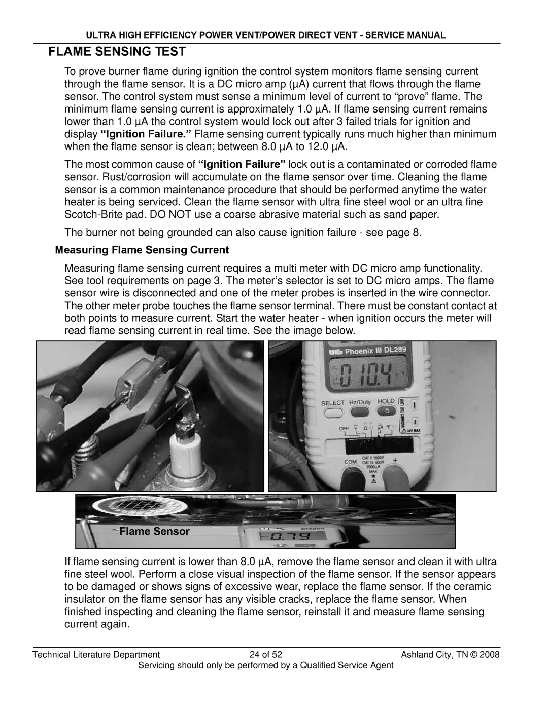
Measuring flame sensing current requires a multi meter with DC micro amp functionality. See tool requirements on page 3. The meter’s selector is set to DC micro amps. The flame sensor wire is disconnected and one of the meter probes is inserted in the wire connector. The other meter probe touches the flame sensor terminal. There must be constant contact at both points to measure current. Start the water heater - when ignition occurs the meter will read flame sensing current in real time. See the image below.
Flame Sensor
If flame sensing current is lower than 8.0 µA, remove the flame sensor and clean it with ultra fine steel wool. Perform a close visual inspection of the flame sensor. If the sensor appears to be damaged or shows signs of excessive wear, replace the flame sensor. If the ceramic insulator on the flame sensor has any visible cracks, replace the flame sensor. When finished inspecting and cleaning the flame sensor, reinstall it and measure flame sensing current again.
Technical Literature Department | 24 of 52 | Ashland City, TN © 2008 |
Servicing should only be performed by a Qualified Service Agent |
| |