ULTRA HIGH EFFICIENCY POWER VENT/POWER DIRECT VENT - SERVICE MANUAL
FAULT MESSAGES (CONT)
| DISPLAYED MESSAGE |
|
| CHECK/REPAIR |
| CONDITION/INDICATES |
|
| |
|
|
|
| |
|
|
|
|
|
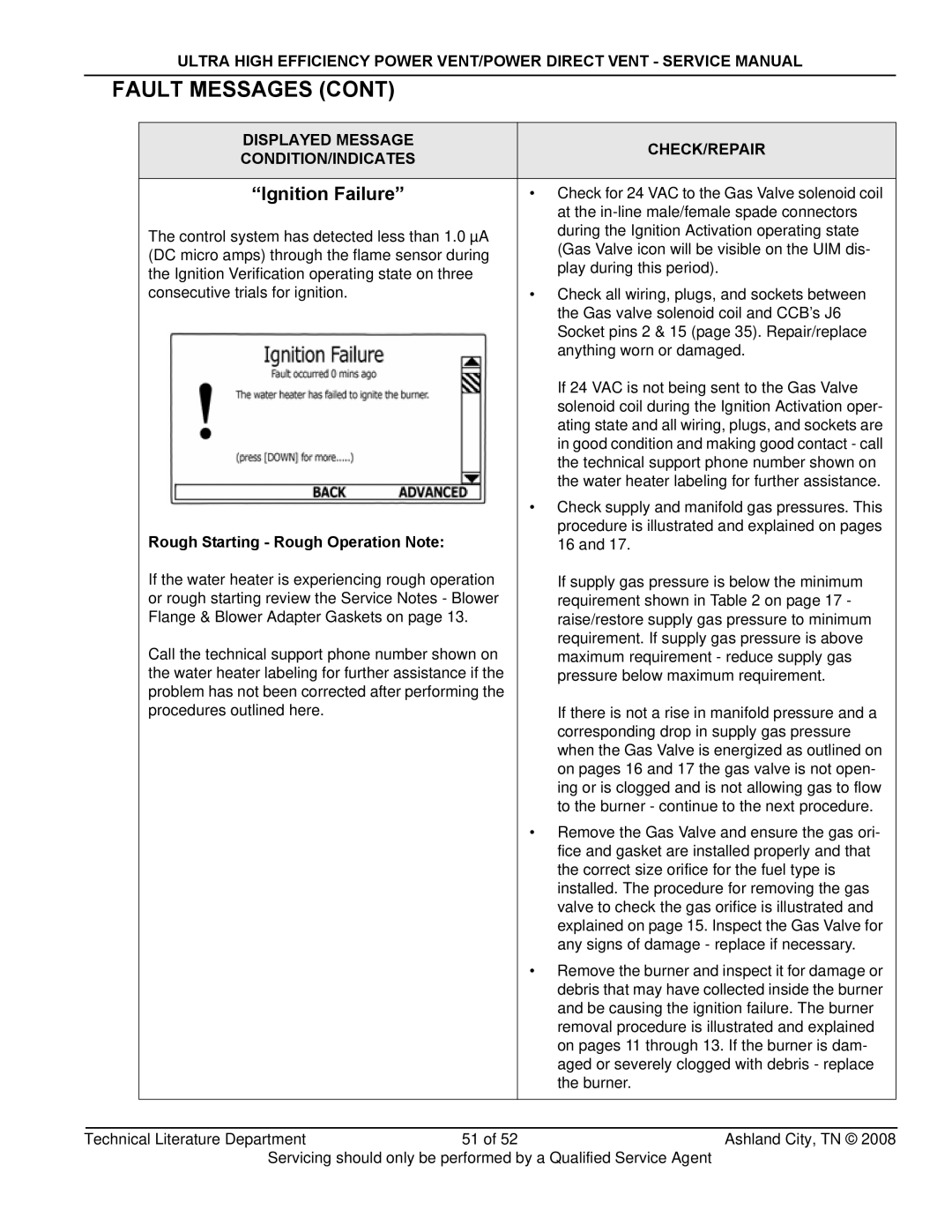
| “Ignition Failure” |
|
| • Check for 24 VAC to the Gas Valve solenoid coil |
|
|
|
| at the |
| The control system has detected less than 1.0 µA |
| during the Ignition Activation operating state | |
|
| (Gas Valve icon will be visible on the UIM dis- | ||
| (DC micro amps) through the flame sensor during |
| ||
|
| play during this period). | ||
| the Ignition Verification operating state on three |
| ||
|
|
| ||
| consecutive trials for ignition. |
|
| • Check all wiring, plugs, and sockets between |
|
|
|
| the Gas valve solenoid coil and CCB’s J6 |
|
|
|
| Socket pins 2 & 15 (page 35). Repair/replace |
|
|
|
| anything worn or damaged. |
|
|
|
| If 24 VAC is not being sent to the Gas Valve |
|
|
|
| solenoid coil during the Ignition Activation oper- |
|
|
|
| ating state and all wiring, plugs, and sockets are |
|
|
|
| in good condition and making good contact - call |
|
|
|
| the technical support phone number shown on |
|
|
|
| the water heater labeling for further assistance. |
|
|
|
| • Check supply and manifold gas pressures. This |
| Rough Starting - Rough Operation Note: |
|
| procedure is illustrated and explained on pages |
|
|
| 16 and 17. | |
| If the water heater is experiencing rough operation |
| If supply gas pressure is below the minimum | |
| or rough starting review the Service Notes - Blower |
| requirement shown in Table 2 on page 17 - | |
| Flange & Blower Adapter Gaskets on page 13. |
| raise/restore supply gas pressure to minimum | |
| Call the technical support phone number shown on |
| requirement. If supply gas pressure is above | |
|
| maximum requirement - reduce supply gas | ||
| the water heater labeling for further assistance if the |
| pressure below maximum requirement. | |
| problem has not been corrected after performing the |
|
| |
| procedures outlined here. |
|
| If there is not a rise in manifold pressure and a |
|
|
|
| corresponding drop in supply gas pressure |
|
|
|
| when the Gas Valve is energized as outlined on |
|
|
|
| on pages 16 and 17 the gas valve is not open- |
|
|
|
| ing or is clogged and is not allowing gas to flow |
|
|
|
| to the burner - continue to the next procedure. |
|
|
|
| • Remove the Gas Valve and ensure the gas ori- |
|
|
|
| fice and gasket are installed properly and that |
|
|
|
| the correct size orifice for the fuel type is |
|
|
|
| installed. The procedure for removing the gas |
|
|
|
| valve to check the gas orifice is illustrated and |
|
|
|
| explained on page 15. Inspect the Gas Valve for |
|
|
|
| any signs of damage - replace if necessary. |
|
|
|
| • Remove the burner and inspect it for damage or |
|
|
|
| debris that may have collected inside the burner |
|
|
|
| and be causing the ignition failure. The burner |
|
|
|
| removal procedure is illustrated and explained |
|
|
|
| on pages 11 through 13. If the burner is dam- |
|
|
|
| aged or severely clogged with debris - replace |
|
|
|
| the burner. |
|
|
|
|
|
|
|
|
|
|
Technical Literature Department | 51 of 52 | Ashland City, TN © 2008 | ||
Servicing should only be performed by a Qualified Service Agent