B.3.5.5 Zone 3 Signal Descriptions
TABLE
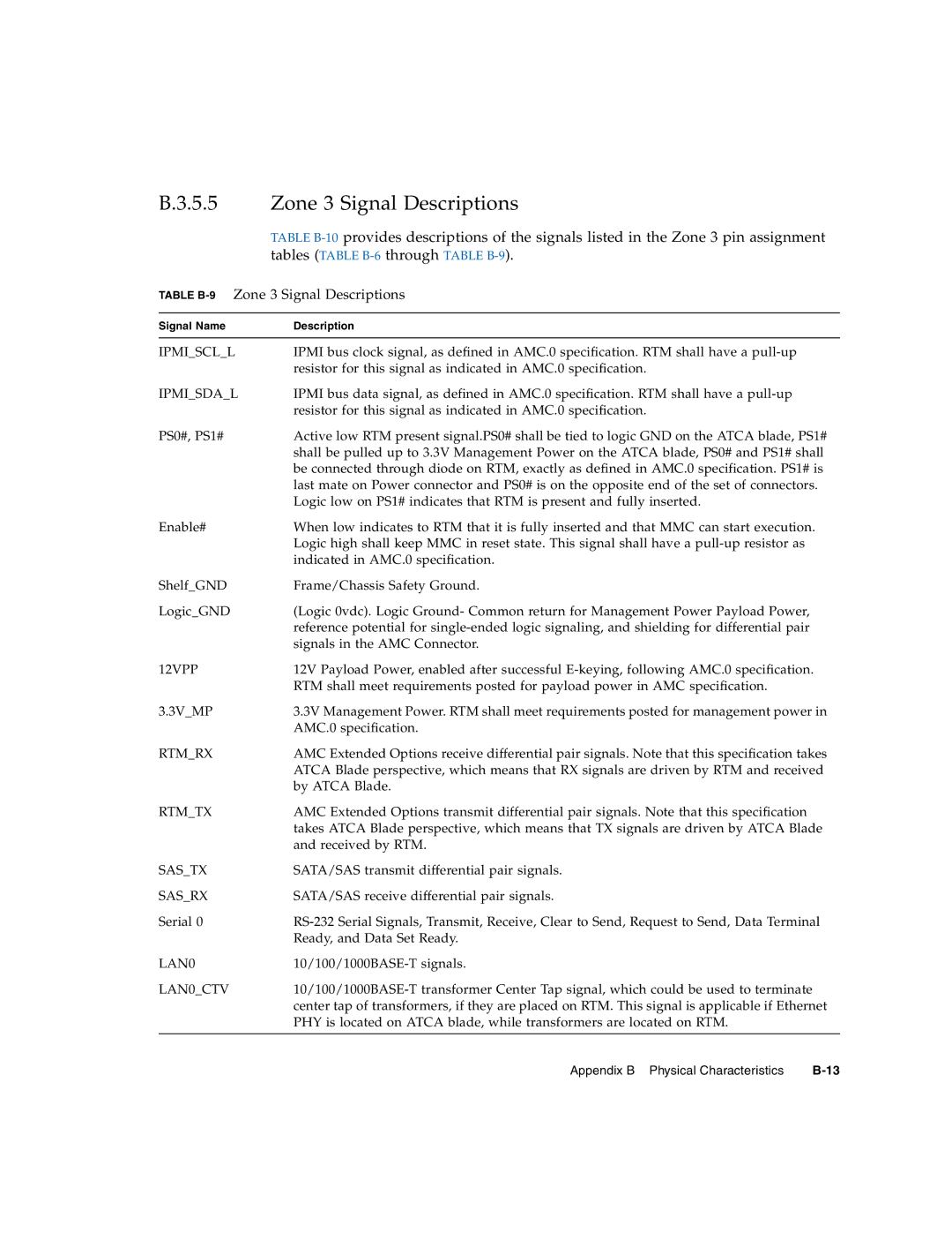
TABLE B-9 Zone 3 Signal Descriptions
Signal Name | Description |
|
|
IPMI_SCL_L | IPMI bus clock signal, as defined in AMC.0 specification. RTM shall have a |
| resistor for this signal as indicated in AMC.0 specification. |
IPMI_SDA_L | IPMI bus data signal, as defined in AMC.0 specification. RTM shall have a |
| resistor for this signal as indicated in AMC.0 specification. |
PS0#, PS1# | Active low RTM present signal.PS0# shall be tied to logic GND on the ATCA blade, PS1# |
| shall be pulled up to 3.3V Management Power on the ATCA blade, PS0# and PS1# shall |
| be connected through diode on RTM, exactly as defined in AMC.0 specification. PS1# is |
| last mate on Power connector and PS0# is on the opposite end of the set of connectors. |
| Logic low on PS1# indicates that RTM is present and fully inserted. |
Enable# | When low indicates to RTM that it is fully inserted and that MMC can start execution. |
| Logic high shall keep MMC in reset state. This signal shall have a |
| indicated in AMC.0 specification. |
Shelf_GND | Frame/Chassis Safety Ground. |
Logic_GND | (Logic 0vdc). Logic Ground- Common return for Management Power Payload Power, |
| reference potential for |
| signals in the AMC Connector. |
12VPP | 12V Payload Power, enabled after successful |
| RTM shall meet requirements posted for payload power in AMC specification. |
3.3V_MP | 3.3V Management Power. RTM shall meet requirements posted for management power in |
| AMC.0 specification. |
RTM_RX | AMC Extended Options receive differential pair signals. Note that this specification takes |
| ATCA Blade perspective, which means that RX signals are driven by RTM and received |
| by ATCA Blade. |
RTM_TX | AMC Extended Options transmit differential pair signals. Note that this specification |
| takes ATCA Blade perspective, which means that TX signals are driven by ATCA Blade |
| and received by RTM. |
SAS_TX | SATA/SAS transmit differential pair signals. |
SAS_RX | SATA/SAS receive differential pair signals. |
Serial 0 | |
| Ready, and Data Set Ready. |
LAN0 | |
LAN0_CTV | |
| center tap of transformers, if they are placed on RTM. This signal is applicable if Ethernet |
| PHY is located on ATCA blade, while transformers are located on RTM. |
|
|
Appendix B Physical Characteristics |