Sun Fire V100 Server User’s Guide
Please Recycle
Contents
Managing the Sun Fire V100 Server From the Solaris Prompt
Powering On and Configuring the Sun Fire V100 Server
Managing the Sun Fire V100 Server From the lom Prompt
Troubleshooting 99 Diagnostic Tools
Reinstalling the Solaris Operating Environment
Interpreting the LEDs
Removing and Replacing Components
Vi Sun Fire V100 Server User’s Guide December
Figures
Viii Sun Fire V100 Server User’s Guide December
102
Tables
Sun Fire V100 Server User’s Guide December
Preface
Part I Installation and Configuration
How This Book Is Organized
Part II Remote and Local Management
Part IV Appendixes
Using Unix Commands
Part III Maintenance and Troubleshooting
Shell Prompts
Typographic Conventions
Safety Precautions
Accessing Sun Documentation Online
Ordering Sun Documentation
Sun Welcomes Your Comments
Modifications to Equipment
Symbols
Xvi Sun Fire V100 Server User’s Guide December
PA RT I Installation and Configuration
Page
Introducing the Sun Fire Server
1The Sun Fire V100 server
Overview of the Sun Fire V100 Server
Preinstalled Software
Contents of the Ship Kit
Optional Components
2Customer Installable Hardware
Installation Quick Start
Sun Fire V100 Server User’s Guide December
Installing the Sun Fire V100 Server Into a Rack
Choosing Between a Rack and a Cabinet
Thermal issues
19-Inch Rackmounting Kit
Security
1Cable Management Bracket
To Assemble the Slides and Mount the Server
Sun Fire V100 Server User’s Guide December
Installing the Sun Fire V100 Server Into a Rack
Sun Fire V100 Server User’s Guide December
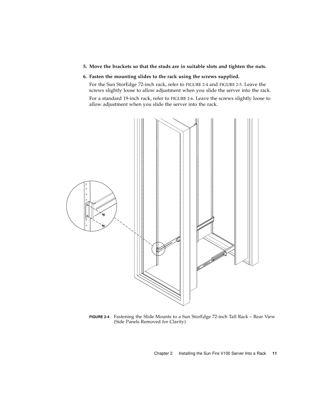
6Fastening the Slide Mounts to a Standard 19-inch Rack
Slide the server into the rack see Figure
Sun Fire V100 Server User’s Guide December
To Fit the Cable Management Bracket
Tips for Using a Sun StorEdge 72-inch Rack
To Connect the Cables to the Server
Connecting the Cables
Connect the power cord
Connect the server to a maximum of two Ethernet hubs
Connect a serial device
Communicating With the Server
Which Is the Appropriate Serial Port?
Setting Up a Console Connection to the Server
Serial Port Pin Arrangement
1Server Serial Ports
1Serial Port Pins 1 to
Serial Connection Settings
4Pin Crossovers in the Sun DB-25 25-Pin Adapter
Serial Adapters
3Serial Adapters
5Pin Crossovers in the DB-9 9-Pin Adapter
To Use the DB-25 Adapter
To Connect to the Server Using an Ascii Terminal
To Connect to the Server Using a Sun Workstation
Make the setting changes shown below
Connecting to the Server Using a Terminal Server
Connecting to a Cisco Terminal Server
6Pin Crossovers for Connecting to a Typical Terminal Server
Connecting to Other Terminal Servers
To Connect to the Server
Set Up New Session window Name the session Choose an icon
Click OK
To Set Up the Hardware
Connecting to the Server Using a Handheld Device
To Set Up the Software
Go to the Applications menu Click the Online icon
Click On
Choose Menu Options Terminal and make the following settings
To Use Macros
Using the Arrow Keys
7Example PalmOS Terminal Emulator Macros
Shows some example macros
Powering On and Configuring Sun Fire V100 Server
Powering On and Configuring the Server
Lom poweron
Lom poweron
To Clear the Configuration and Start Again
To Power On a Standalone Server for the First Time
At the Solaris prompt, type
Boot the server into the Solaris environment by typing
If you are at the lom prompt, go to the ok prompt by typing
Standby
Using the Power On/Standby Switch
Sun Fire V100 Server User’s Guide December
PA RT II Remote and Local Management
Page
Introduction to Lights-Out Management
Managing the Sun Fire V100 Server From the lom Prompt
Using LOM Commands
To Power On the Server or to Power Down to Standby Mode
Powering On or Resetting the Server From the LOM Shell
To power on the server, type
To power the server down to standby mode, type
To Exit From the lom Prompt
To Display the lom Prompt
Controlling the Server’s Booting Behavior
To Reset the Server
To reset the server, type
To Display the ok or kadb Prompt
Boot Modes Available
Monitoring the Server From the LOM Shell
To Check the Current Status of All Components
Code Example 5-1Sample Output From the environment Command
To Check How Long the Server Has Been Running
Type
Viewing the LOM Event Log
To View the Last 10 Events in the Event Log
To View All Events From the First to the nth Event Logged
To View the Entire Event Log
To see the last five events, type
Verifying That a Component Has Been Fixed
To Check the Status of a Component
Permissions Available for LOM Users
Setting Up LOM Privileges for Named Users
To Create a LOM User Account
To Specify the Password for a LOM User Account
To Delete a LOM User Account
To Change Your Own User Password
To View the Details of a LOM User Account
One, two, or three parameters
To Specify Permissions for a Named User
All four parameters for example, userperm cuar
To Turn the Fault LED On and Off
Setting the LOM Configurable Variables
To Set an Alarm Flag
Turn the alarm on by typing
Enable event reporting by typing
Turn the alarm off by typing
Disable event reporting by typing
To Stop LOM Sending Event Reports to the Serial A/LOM Port
To Dedicate Serial A/LOM to LOM
Separating LOM From the Console on the Serial A/LOM Port
To Share the Serial A/LOM Port Between LOM and the Console
Viewing Event Reports That LOM Sends to syslogd
2LOM Commands
LOM Shell Command List
Fatal
Info
Components
Sun Fire V100 Server User’s Guide December
Managing the Sun Fire V100 Server From the Solaris Prompt
Monitoring the System From the Solaris Prompt
To Check the Power Supply Unit lom -p
To View the LOM Online Documentation
To view the manual pages for the LOM utility, type
To Check the Fan Status lom -f
# lom
To Check the Internal Temperature
To Check Whether the Fault LED and Alarms Are On or Off
# lom -c
To View the Configuration of LOM
OFF
To see the event log, type
To View the Event Log lom -e
To Configure the LOM ASR
Configuring Automatic Server Restart
Etc/rc2.d/S25lom script
# lom -W on,40000,10000
Other LOM Tasks You Can Perform From the Solaris Prompt
To Turn the Alarms On and Off lom -A
To Turn the Fault LED On and Off lom -F
To turn the Fault LED off, type
To turn serial event reporting on again, type
To Upgrade LOM Firmware lom -G default
To Make the LOM Interface Backward Compatible lom -B
PA RT III Maintenance and Troubleshooting
Page
Interpreting the LEDs
Fault LED Amber
Power LED Green
Interpreting the Front- and Back-Panel LEDs
Front-Panel LEDs
Power LED
Fault LED
Back-Panel LEDs
Ethernet port
2Back-Panel Power and Fault LEDs
To Turn the Fault LED On or Off
Removing and Replacing Components
Adding Components or Replacing a Server
Replacing the System Configuration Card
To Swap the System Configuration Card SCC Between Servers
Adding or Changing Internal Components
1The System Configuration Card Slot
Shut down the Solaris environment from the console
To Change Components In a Sun Fire Server That Is In Use
3Removing the Top Cover
To Remove the Top Cover
4Replacing the Top Cover
To Replace the Top Cover
Tighten the captive screw on the back of the unit
Memory Installation and Removal
To Install and Remove Memory
To Install a Hard Disk Drive
Installing and Removing the Hard Disk Drive
7Removing the HDD Placeholder
To Remove a Hard Disk Drive
8Installing a Hard Disk Drive
Removing and Replacing Components
Sun Fire V100 Server User’s Guide December
Environment
Reinstalling the Solaris Operating
Reinstalling the Lights-Out Management Software
Reinstalling the Solaris Operating Environment
Troubleshooting
Post Diagnostics
Diagnostic Tools
This displays the OpenBoot Diagnostics menu
OpenBoot Diagnostics
Function of each test is shown below
1Open Boot Diagnostics Tests
2SunVTS Tests
SunVTS
Remotely log in to the server as superuser or root Type
Installing SunVTS
Power On Failure
Problems You Might Encounter
Cannot Set Up a Console Connection to a Server
No LOM Messages Displayed at the Terminal
Problems Connecting to the Server Using a Handheld Device
Cannot Display the lom Prompt Using the #. Escape Sequence
IDE Controller Failure
Jumper Settings
What software is preinstalled?
Frequently Asked Questions
What information does the System Configuration Card hold?
Where do I connect my monitor, keyboard, and mouse?
Troubleshooting
Sun Fire V100 Server User’s Guide December
PA RT IV Appendixes
Page
Physical and Environmental Specifications
Environmental Specifications
Physical Specifications
Table A-1Sun Fire V100 Server Physical Specifications
Acoustic Noise Generated
Environmental Compliance Information
Operating Power Statistics
Table A-2Operating Power Statistics
Calculating Heat Dissipation
Calculating Power Consumption
Table A-3Estimated Power Consumption of Server Components
Configuring LOM Driver
LOM Device Driver and Script Files
Table B-1LOM Configuration File Parameters
Configuring the LOM Device Driver
Boolean Causes LOM to disable its
Boolean Causes LOM to return the user
Sun Fire V100 Server User’s Guide December
Index
Index-126Sun Fire V100 Server User’s Guide December
Index-127
Index-128Sun Fire V100 Server User’s Guide December