PTZ (continued)
Bit Settings
There are several ‘bit’ settings to configure - again, these must match the required settings for the camera system. Consult the camera documentation to learn these values.
Data Bit
A DATA BIT is one part of a set of data sent to the camera to tell it which way to point. Some PTZ cameras like very short packets of information, others require longer packets of information at a time.
We can set this by choosing the number of DATA BITS to form a packet. This value must be matched to the required value for your camera system. Simply enter the camera systems preferred value into the
Stop Bit
Each packet of data sent needs either one or two stop bits attached to the end, to tell the camera system when a packet ends and a new one begins.
This should be matched to the requirements of the PTZ camera system. Choose 1 or 2 as required for your PTZ camera system.
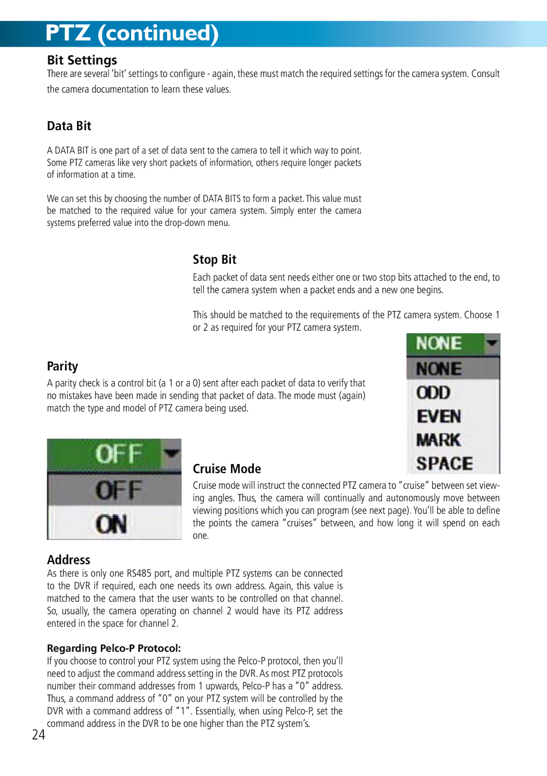
Parity
A parity check is a control bit (a 1 or a 0) sent after each packet of data to verify that no mistakes have been made in sending that packet of data. The mode must (again) match the type and model of PTZ camera being used.
Cruise Mode
Cruise mode will instruct the connected PTZ camera to “cruise” between set view- ing angles. Thus, the camera will continually and autonomously move between viewing positions which you can program (see next page). You’ll be able to define the points the camera “cruises” between, and how long it will spend on each one.
Address
As there is only one RS485 port, and multiple PTZ systems can be connected to the DVR if required, each one needs its own address. Again, this value is matched to the camera that the user wants to be controlled on that channel. So, usually, the camera operating on channel 2 would have its PTZ address entered in the space for channel 2.
Regarding Pelco-P Protocol:
If you choose to control your PTZ system using the
24 command address in the DVR to be one higher than the PTZ system’s.