Table
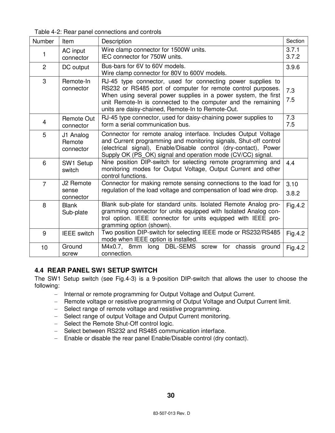
Number | Item | Description | Section | |
1 | AC input | Wire clamp connector for 1500W units. | 3.7.1 | |
connector | IEC connector for 750W units. | 3.7.2 | ||
| ||||
2 | DC output | 3.9.6 | ||
|
| Wire clamp connector for 80V to 600V models. |
| |
3 |
| |||
| connector | RS232 or RS485 port of computer for remote control purposes. | 7.3 | |
|
| When using several power supplies in a power system, the first | ||
|
| 7.5 | ||
|
| unit | ||
|
|
| ||
|
| units are |
| |
4 | Remote Out | 7.3 | ||
connector | form a serial communication bus. | 7.5 | ||
| ||||
5 | J1 Analog | Connector for remote analog interface. Includes Output Voltage |
| |
| Remote | and Current programming and monitoring signals, |
| |
| connector | (electrical signal), Enable/Disable control |
| |
|
| Supply OK (PS_OK) signal and operation mode (CV/CC) signal. |
| |
6 | SW1 Setup | Nine position | 4.4 | |
| switch | monitoring modes for Output Voltage, Output Current and other |
| |
|
| control functions. |
| |
7 | J2 Remote | Connector for making remote sensing connections to the load for | 3.10 | |
| sense | regulation of the load voltage and compensation of load wire drop. | 3.8.2 | |
| connector |
| ||
|
|
| ||
8 | Blank | Blank | Fig.4.2 | |
| gramming connector for units equipped with Isolated Analog con- |
| ||
|
| trol option. IEEE connector for units equipped with IEEE pro- |
| |
|
| gramming option (shown). |
| |
9 | IEEE switch | Two position | Fig.4.2 | |
|
| mode when IEEE option is installed. |
| |
10 | Ground | M4x0.7, 8mm long | Fig.4.2 | |
| screw | connection. |
|
4.4 REAR PANEL SW1 SETUP SWITCH
The SW1 Setup switch (see
Internal or remote programming for Output Voltage and Output Current.
Remote voltage or resistive programming of Output Voltage and Output Current limit.
Select range of remote voltage and resistive programming.
Select range of output Voltage and Output Current monitoring.
Select the Remote
Select between RS232 and RS485 communication interface.
Enable or disable the rear panel Enable/Disable control (dry contact).
30