1 2
3 4 5
6 7
8
9
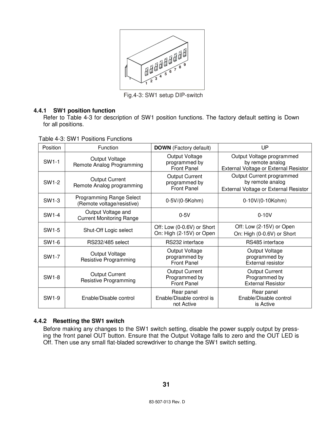
Fig.4-3: SW1 setup DIP-switch
4.4.1SW1 position function
Refer to Table
Table
Position | Function | DOWN (Factory default) | UP | |
Output Voltage | Output Voltage | Output Voltage programmed | ||
programmed by | by remote analog | |||
Remote Analog Programming | ||||
| Front Panel | External Voltage or External Resistor | ||
|
| |||
| Output Current | Output Current | Output Current programmed | |
programmed by | by remote analog | |||
Remote Analog programming | ||||
| Front Panel | External Voltage or External Resistor | ||
|
| |||
Programming Range Select | ||||
(Remote voltage/resistive) | ||||
|
|
| ||
Output Voltage and | ||||
Current Monitoring Range | ||||
|
|
| ||
Off: Low | Off: Low | |||
On: High | On: High | |||
|
| |||
RS232/485 select | RS232 interface | RS485 interface | ||
|
|
|
| |
| Output Voltage | Output Voltage | Output Voltage | |
programmed by | programmed by | |||
Resistive Programming | ||||
| Front Panel | External resistor | ||
|
| |||
| Output Current | Output Current | Output Current | |
Programmed by | Programmed by | |||
Resistive Programming | ||||
| Front Panel | External Resistor | ||
|
| |||
|
| Rear panel | Rear panel | |
Enable/Disable control | Enable/Disable control is | Enable/Disable control | ||
|
| not Active | is Active |
4.4.2Resetting the SW1 switch
Before making any changes to the SW1 switch setting, disable the power supply output by press- ing the front panel OUT button. Ensure that the Output Voltage falls to zero and the OUT LED is Off. Then use any small
31