|
|
|
|
|
|
|
|
|
| +S |
|
|
|
|
|
|
|
|
|
| |
|
|
|
|
|
|
|
|
|
| Twisted |
|
|
|
|
|
|
|
|
|
| pair |
To |
|
|
|
| +S | |||||
|
|
|
| As short as possible | ||||||
|
|
|
|
|
|
|
| +V | ||
SLAVE#2 | MASTER |
|
| |||||||
|
|
| +S | |||||||
POWER SUPPLY | POWER SUPPLY |
|
| Twisted | ||||||
|
|
| pair | |||||||
|
|
|
|
|
|
|
| |||
|
|
|
|
| P |
|
|
|
| |
|
|
|
|
| IPGM |
|
|
|
| |
|
|
|
|
| ||||||
| SLAVE#1 |
|
| +V |
| |||||
| POWER SUPPLY |
|
| |||||||
|
|
|
|
|
|
|
|
|
| |
|
| +LS +S |
| |||||||
|
|
|
|
|
|
|
|
|
|
|
LOAD
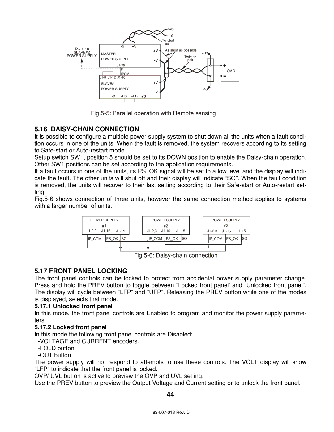
Fig.5-5: Parallel operation with Remote sensing
5.16 DAISY-CHAIN CONNECTION
It is possible to configure a multiple power supply system to shut down all the units when a fault condi- tion occurs in one of the units. When the fault is removed, the system recovers according to its setting to
Setup switch SW1, position 5 should be set to its DOWN position to enable the
If a fault occurs in one of the units, its PS_OK signal will be set to a low level and the display will indi- cate the fault. The other units will shut off and their display will indicate “SO”. When the fault condition is removed, the units will recover to their last setting according to their
Fig.5-6 shows connection of three units, however the same connection method applies to systems with a larger number of units.
POWER SUPPLY
#1
POWER SUPPLY
#2
POWER SUPPLY
#3
IF_COM
PS_OK | SO | IF_COM PS_OK SO | IF_COM | PS_OK | SO |
|
|
|
|
| |
5.17 FRONT PANEL LOCKING
The front panel controls can be locked to protect from accidental power supply parameter change. Press and hold the PREV button to toggle between “Locked front panel’ and “Unlocked front panel”. The display will cycle between “LFP” and “UFP”. Releasing the PREV button while one of the modes is displayed, selects that mode.
5.17.1 Unlocked front panel
In this mode, the front panel controls are Enabled to program and monitor the power supply parame- ters.
5.17.2 Locked front panel
In this mode the following front panel controls are Disabled:
The power supply will not respond to attempts to use these controls. The VOLT display will show “LFP” to indicate that the front panel is locked.
OVP/ UVL button is active to preview the OVP and UVL setting.
Use the PREV button to preview the Output Voltage and Current setting or to unlock the front panel.
44