6.6 REMOTE MONITORING OF OUTPUT VOLTAGE AND CURRENT
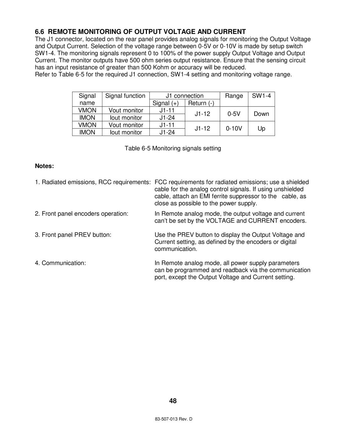
The J1 connector, located on the rear panel provides analog signals for monitoring the Output Voltage and Output Current. Selection of the voltage range between
Refer to Table
Signal | Signal function | J1 connection | Range | |||
name |
| Signal (+) | Return |
|
| |
VMON | Vout monitor | Down | ||||
IMON | Iout monitor | |||||
|
|
| ||||
VMON | Vout monitor | Up | ||||
IMON | Iout monitor | |||||
|
|
| ||||
Table
Notes:
1.Radiated emissions, RCC requirements:
2.Front panel encoders operation:
3.Front panel PREV button:
FCC requirements for radiated emissions; use a shielded cable for the analog control signals. If using unshielded cable, attach an EMI ferrite suppressor to the cable, as close as possible to the power supply.
In Remote analog mode, the output voltage and current can’t be set by the VOLTAGE and CURRENT encoders.
Use the PREV button to display the Output Voltage and Current setting, as defined by the encoders or digital communication.
4. Communication: | In Remote analog mode, all power supply parameters |
| can be programmed and readback via the communication |
| port, except the Output Voltage and Current setting. |
48