6.Connection to the load
In parallel operation, power supplies can be connected in local or remote sensing. Refer to Fig. 5- 4 and
5.15.2 Advanced parallel operation
In this method, multiple supplies can be configured to parallel operation as a single power supply. The total load current and output voltage are displayed by the Master unit and can be readback from the Master unit. The Slave units display only their operating status (On, Off or Fault condition).
Refer to the following procedure to configure multiple supplies for advanced parallel operation.
1.Advanced parallel configuration
SW1 position 2 - Down in the Master Supply and up in all Slave Supplies.
Connect a short between
Connect
The following
Switch SW1 position 5 should be in its down position for all power supplies (See Sec- tion 5.6)
Connect
Connect
Connect
Connect
Connect
Select Local or Remote sense - Ref. Figures
2.Setting the units as Master or Slave
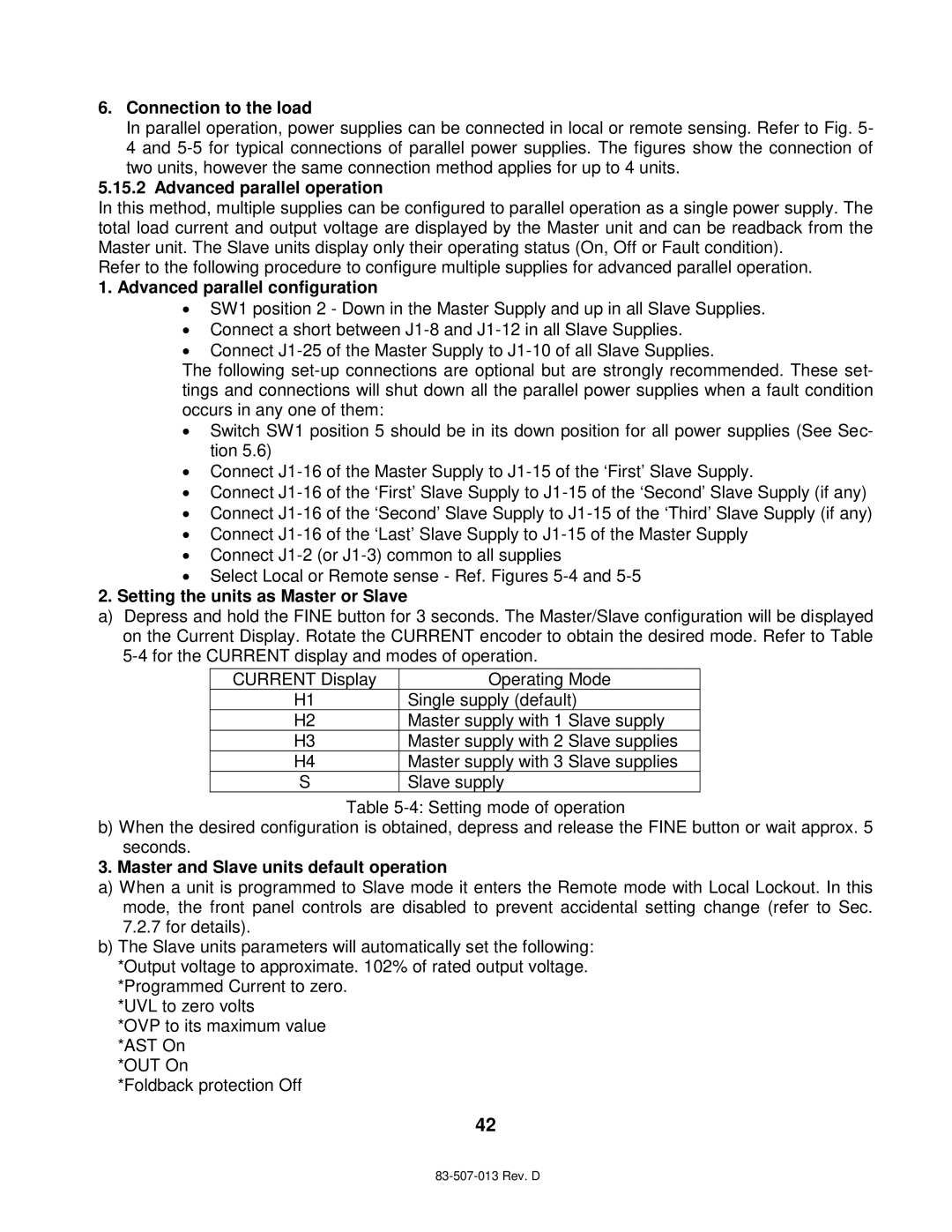
a)Depress and hold the FINE button for 3 seconds. The Master/Slave configuration will be displayed on the Current Display. Rotate the CURRENT encoder to obtain the desired mode. Refer to Table
CURRENT Display | Operating Mode | |
H1 | Single supply (default) | |
H2 | Master supply with 1 | Slave supply |
H3 | Master supply with 2 | Slave supplies |
H4 | Master supply with 3 | Slave supplies |
S | Slave supply |
|
Table
b)When the desired configuration is obtained, depress and release the FINE button or wait approx. 5 seconds.
3. Master and Slave units default operation
a)When a unit is programmed to Slave mode it enters the Remote mode with Local Lockout. In this mode, the front panel controls are disabled to prevent accidental setting change (refer to Sec.
7.2.7for details).
b)The Slave units parameters will automatically set the following: *Output voltage to approximate. 102% of rated output voltage. *Programmed Current to zero.
*UVL to zero volts
*OVP to its maximum value *AST On
*OUT On
*Foldback protection Off
42