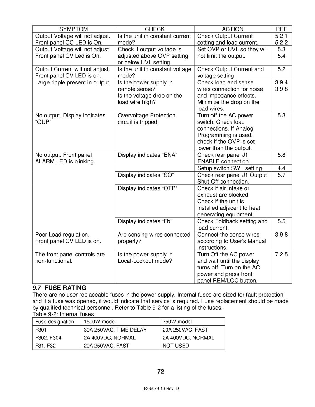
SYMPTOM | CHECK | ACTION | REF |
Output Voltage will not adjust. | Is the unit in constant current | Check Output Current | 5.2.1 |
Front panel CC LED is On. | mode? | setting and load current. | 5.2.2 |
Output Voltage will not adjust | Check if output voltage is | Set OVP or UVL so they will | 5.3 |
Front panel CV Led is On. | adjusted above OVP setting | not limit the output. | 5.4 |
| or below UVL setting. |
|
|
Output Current will not adjust. | Is the unit in constant voltage | Check Output Current and | 5.2 |
Front panel CV LED is on. | mode? | voltage setting |
|
Large ripple present in output. | Is the power supply in | Check load and sense | 3.9.4 |
| remote sense? | wires connection for noise | 3.9.8 |
| Is the voltage drop on the | and impedance effects. |
|
| load wire high? | Minimize the drop on the |
|
|
| load wires. |
|
No output. Display indicates | Overvoltage Protection | Turn off the AC power | 5.3 |
“OUP” | circuit is tripped. | switch. Check load |
|
|
| connections. If Analog |
|
|
| Programming is used, |
|
|
| check if the OVP is set |
|
|
| lower than the output. |
|
No output. Front panel | Display indicates “ENA” | Check rear panel J1 | 5.8 |
ALARM LED is blinking. |
| ENABLE connection. |
|
|
| Setup switch SW1 setting. | 4.4 |
| Display indicates “SO” | Check rear panel J1 Output | 5.7 |
|
|
| |
| Display indicates “OTP” | Check if air intake or |
|
|
| exhaust are blocked. |
|
|
| Check if the unit is |
|
|
| installed adjacent to heat |
|
|
| generating equipment. |
|
| Display indicates “Fb” | Check Foldback setting and | 5.5 |
|
| load current. |
|
Poor Load regulation. | Are sensing wires connected | Connect the sense wires | 3.9.8 |
Front panel CV LED is on. | properly? | according to User’s Manual |
|
|
| instructions. |
|
The front panel controls are | Is the power supply in | Turn Off the AC power | 7.2.5 |
and wait until the display |
| ||
|
| turns off. Turn on the AC |
|
|
| power and press front |
|
|
| panel REM/LOC button. |
|
9.7 FUSE RATING
There are no user replaceable fuses in the power supply. Internal fuses are sized for fault protection and if a fuse was opened, it would indicate that service is required. Fuse replacement should be made by qualified technical personnel. Refer to Table
Table
Fuse designation | 1500W model | 750W model | |
F301 | 30A | 250VAC, TIME DELAY | 20A 250VAC, FAST |
F302, F304 | 2A 400VDC, NORMAL | 2A 400VDC, NORMAL | |
F31, F32 | 20A | 250VAC, FAST | NOT USED |
72