SPRS293A − OCTOBER 2005 − REVISED NOVEMBER 2005


Terminal Functions (Continued)


PIN


SIGNAL


NO.

TYPE

IPD/


DESCRIPTION


NAME


GDP/

IPU


ZDP


RESETS AND INTERRUPTS


Device reset. When using Boundary Scan mode on the device, drive the EMU[1:0] and

RESET


RESET


A13

I

−−

pins low.


This pin does not have an IPU.


Nonmaskable interrupt


NMI


C13

I

IPD

Edge-driven (rising edge)


Any noise on the NMI pin may trigger an NMI interrupt; therefore, if the NMI pin is not used, it is


recommended that the NMI pin be grounded versus relying on the IPD.


EXT_INT7


E3


General-purpose input/output pins (I/O/Z) which also function as external interrupts (default)


EXT_INT6


D2


I

IPU

Edge-driven


EXT_INT5


C1

Polarity independently selected via the External Interrupt Polarity Register


bits (EXTPOL.[3:0]), in addition to the GPIO registers.


EXT_INT4


C2


EMIF − CONTROL SIGNALS COMMON TO ALL TYPES OF MEMORY #


CE3


V6

O/Z

IPU


Memory space enables


CE2


W6

O/Z

IPU


Enabled by bits 28 through 31 of the word address


CE1


W18

O/Z

IPU


Only one asserted during any external data access


V17

O/Z

IPU


CE0


Byte-enable control


BE1


U19

O/Z

IPU


Decoded from the two lowest bits of the internal address


Byte-write enables for most types of memory


BE0


V20

O/Z

IPU


Can be directly connected to SDRAM read and write mask signal (SDQM)


EMIF − BUS ARBITRATION #


HOLDA


J18

O

IPU

Hold-request-acknowledge to the host


J17

I

IPU

Hold request from the host


HOLD


BUSREQ


J19

O

IPU

Bus request output


EMIF −

ASYNCHRONOUS/SYNCHRONOUS DRAM/SYNCHRONOUS BURST SRAM MEMORY CONTROL #


ECLKIN


Y11

I

IPD

EMIF input clock


EMIF output clock depends on the EKSRC bit (DEVCFG.[4]) and on EKEN bit


(GBLCTL.[5])


EKSRC = 0

ECLKOUT is based on the internal SYSCLK3 signal


from the clock generator (default).


ECLKOUT


Y10

O

IPD

EKSRC = 1

ECLKOUT is based on the the external EMIF input clock


source pin (ECLKIN)


EKEN = 0

ECLKOUT held low


EKEN = 1

ECLKOUT enabled to clock (default)

I = Input, O = Output, Z = High impedance, S = Supply voltage, GND = Ground, A = Analog signal (PLL Filter)

IPD = Internal pulldown, IPU = Internal pullup. [To oppose the supply rail on these IPD/IPU signal pins, use external pullup or pulldown resistors no greater than 4.4 kand 2.0 k, respectively.]

# To maintain signal integrity for the EMIF signals, serial termination resistors should be inserted into all EMIF output signal lines.

26

POST OFFICE BOX 1443 HOUSTON, TEXAS 77251−1443

Page 26
Image 26
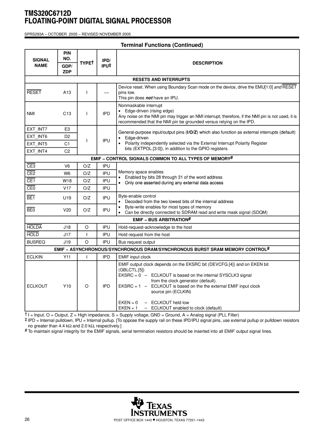
Texas Instruments TMS320C6712D warranty IPD Description Name GDP IPU‡ ZDP Resets and Interrupts, Edge-driven

TMS320C6712D specifications

The Texas Instruments TMS320C6712D is a high-performance, fixed-point digital signal processor (DSP) that belongs to the TMS320C6000 family, well known for its advanced processing capabilities tailored for demanding signal processing applications. Launched in the early 2000s, the C6712D combines high computational power with a rich set of features, making it suitable for a variety of applications such as telecommunications, audio processing, and industrial control systems.

One of the standout characteristics of the TMS320C6712D is its architecture, which is based on a highly efficient VLIW (Very Long Instruction Word) design. This architecture allows the processor to execute multiple instructions in a single clock cycle, significantly increasing performance. The device operates at clock speeds of up to 150 MHz, providing substantial computational throughput that can handle complex algorithms and real-time processing tasks.

Another key feature of the TMS320C6712D is its 32-bit fixed-point processing capabilities, which allows it to perform difficult mathematical computations efficiently. With an instruction set optimized for DSP applications, the processor includes specialized instructions for multiplying and accumulating operations, as well as support for advanced filtering and generation of audio signals.

The C6712D offers an extensive memory architecture, supporting up to 128 MB of external memory via a 32-bit data bus. It features on-chip SRAM, which provides fast access to data and program storage, enhancing the system's overall performance. Additionally, the device includes a powerful set of peripherals, such as dual asynchronous serial ports (UART), I2C interfaces, and DSP-specific interfaces that facilitate connectivity with other components and systems.

Power consumption is another vital aspect of the TMS320C6712D. It incorporates technologies allowing for low-power operation, which is essential for portable and battery-operated devices. The capability to operate in various power modes helps optimize performance while minimizing energy usage.

In conclusion, the Texas Instruments TMS320C6712D is a versatile and powerful DSP that excels in high-performance applications. Its VLIW architecture, fixed-point processing capabilities, extensive memory options, and low power consumption make it an ideal choice for engineers looking to implement complex signal processing tasks efficiently. Whether used in telecommunications, audio processing, or industrial applications, the C6712D remains a reliable and capable solution in the digital signal processing landscape.