Texas Instruments TMS320C6712D warranty Emif big endian mode correctness, Bootmode, Reset

Models: TMS320C6712D

1 102
Download 102 pages 54.97 Kb
Page 60
Image 60

SPRS293A − OCTOBER 2005 − REVISED NOVEMBER 2005

EMIF big endian mode correctness

The device Endian mode pin (LENDIAN) selects the endian mode of operation (little endian or big endian) for the device. Little endian is the default setting.

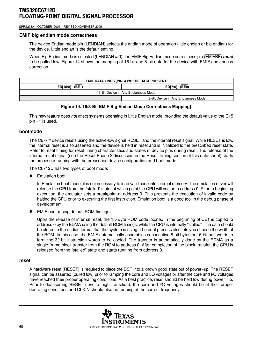
When Big Endian mode is selected (LENDIAN = 0), the EMIF Big Endian mode correctness pin (EMIFBE) must to be pulled low. Figure 14 shows the mapping of 16-bit and 8-bit data for the device with EMIF endianness correction.

EMIF DATA LINES (PINS) WHERE DATA PRESENT

ED[15:8] (BE1)

ED[7:0] (BE0)

16-Bit Device in Any Endianness Mode

8-Bit Device in Any Endianness Mode

Figure 14. 16/8-Bit EMIF Big Endian Mode Correctness Mapping]

This new feature does not affect systems operating in Little Endian mode, providing the default value of the C15 pin =1 is used.

bootmode

The C67xdevice resets using the active-low signal RESET and the internal reset signal. While RESET is low, the internal reset is also asserted and the device is held in reset and is initialized to the prescribed reset state. Refer to reset timing for reset timing characteristics and states of device pins during reset. The release of the internal reset signal (see the Reset Phase 3 discussion in the Reset Timing section of this data sheet) starts the processor running with the prescribed device configuration and boot mode.

The C6712D has two types of boot mode:

DEmulation boot

In Emulation boot mode, it is not necessary to load valid code into internal memory. The emulation driver will release the CPU from the “stalled” state, at which point the CPU will vector to address 0. Prior to beginning execution, the emulator sets a breakpoint at address 0. This prevents the execution of invalid code by halting the CPU prior to executing the first instruction. Emulation boot is a good tool in the debug phase of development.

DEMIF boot (using default ROM timings)

Upon the release of internal reset, the 1K-Byte ROM code located in the beginning of CE1 is copied to address 0 by the EDMA using the default ROM timings, while the CPU is internally “stalled”. The data should be stored in the endian format that the system is using. The boot process also lets you choose the width of the ROM. In this case, the EMIF automatically assembles consecutive 8-bit bytes or 16-bit half-words to form the 32-bit instruction words to be copied. The transfer is automatically done by the EDMA as a single-frame block transfer from the ROM to address 0. After completion of the block transfer, the CPU is released from the “stalled” state and starts running from address 0.

reset

A hardware reset (RESET) is required to place the DSP into a known good state out of power−up. The RESET signal can be asserted (pulled low) prior to ramping the core and I/O voltages or after the core and I/O voltages have reached their proper operating conditions. As a best practice, reset should be held low during power−up. Prior to deasserting RESET (low−to−high transition), the core and I/O voltages should be at their proper operating conditions and CLKIN should also be running at the correct frequency.

60

POST OFFICE BOX 1443 HOUSTON, TEXAS 77251−1443

Page 60
Image 60
Texas Instruments TMS320C6712D Emif big endian mode correctness, Bootmode, Reset, Emif Data Lines Pins Where Data Present

TMS320C6712D specifications

The Texas Instruments TMS320C6712D is a high-performance, fixed-point digital signal processor (DSP) that belongs to the TMS320C6000 family, well known for its advanced processing capabilities tailored for demanding signal processing applications. Launched in the early 2000s, the C6712D combines high computational power with a rich set of features, making it suitable for a variety of applications such as telecommunications, audio processing, and industrial control systems.

One of the standout characteristics of the TMS320C6712D is its architecture, which is based on a highly efficient VLIW (Very Long Instruction Word) design. This architecture allows the processor to execute multiple instructions in a single clock cycle, significantly increasing performance. The device operates at clock speeds of up to 150 MHz, providing substantial computational throughput that can handle complex algorithms and real-time processing tasks.

Another key feature of the TMS320C6712D is its 32-bit fixed-point processing capabilities, which allows it to perform difficult mathematical computations efficiently. With an instruction set optimized for DSP applications, the processor includes specialized instructions for multiplying and accumulating operations, as well as support for advanced filtering and generation of audio signals.

The C6712D offers an extensive memory architecture, supporting up to 128 MB of external memory via a 32-bit data bus. It features on-chip SRAM, which provides fast access to data and program storage, enhancing the system's overall performance. Additionally, the device includes a powerful set of peripherals, such as dual asynchronous serial ports (UART), I2C interfaces, and DSP-specific interfaces that facilitate connectivity with other components and systems.

Power consumption is another vital aspect of the TMS320C6712D. It incorporates technologies allowing for low-power operation, which is essential for portable and battery-operated devices. The capability to operate in various power modes helps optimize performance while minimizing energy usage.

In conclusion, the Texas Instruments TMS320C6712D is a versatile and powerful DSP that excels in high-performance applications. Its VLIW architecture, fixed-point processing capabilities, extensive memory options, and low power consumption make it an ideal choice for engineers looking to implement complex signal processing tasks efficiently. Whether used in telecommunications, audio processing, or industrial applications, the C6712D remains a reliable and capable solution in the digital signal processing landscape.