11.4Control Wires
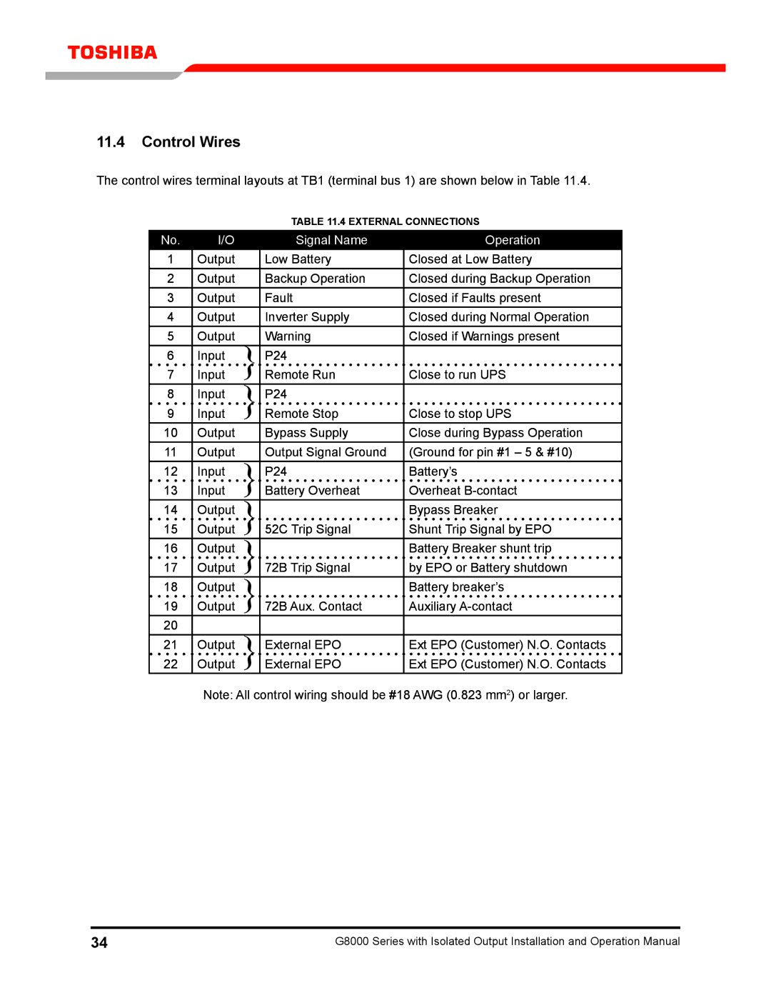
The control wires terminal layouts at TB1 (terminal bus 1) are shown below in Table 11.4.
|
|
|
|
| Table 11.4 EXTERNAL CONNECTIONS | ||
No. |
| I/O |
|
| Signal Name |
| Operation |
1 |
| Output |
|
| Low Battery |
| Closed at Low Battery |
2 |
| Output |
|
| Backup Operation |
| Closed during Backup Operation |
3 |
| Output |
|
| Fault |
| Closed if Faults present |
4 |
| Output |
|
| Inverter Supply |
| Closed during Normal Operation |
5 |
| Output |
|
| Warning |
| Closed if Warnings present |
6 |
| Input | } |
| P24 |
|
|
7 |
| Input |
| Remote Run |
| Close to run UPS | |
|
|
| |||||
8 |
| Input | } |
| P24 |
|
|
9 |
| Input |
| Remote Stop |
| Close to stop UPS | |
|
|
| |||||
10 |
| Output |
|
| Bypass Supply |
| Close during Bypass Operation |
11 |
| Output |
|
| Output Signal Ground |
| (Ground for pin #1 – 5 & #10) |
12 |
| Input | } |
| P24 |
| Battery’s |
13 |
| Input |
| Battery Overheat |
| Overheat | |
|
|
| |||||
14 |
| Output | } |
|
|
| Bypass Breaker |
15 |
| Output |
| 52C Trip Signal |
| Shunt Trip Signal by EPO | |
|
|
| |||||
16 |
| Output | } |
|
|
| Battery Breaker shunt trip |
17 |
| Output |
| 72B Trip Signal |
| by EPO or Battery shutdown | |
|
|
| |||||
18 |
| Output | } |
|
|
| Battery breaker’s |
19 |
| Output |
| 72B Aux. Contact |
| Auxiliary | |
|
|
| |||||
20 |
|
|
|
|
|
|
|
21 |
| Output | } |
| External EPO |
| Ext EPO (Customer) N.O. Contacts |
22 |
| Output |
| External EPO |
| Ext EPO (Customer) N.O. Contacts | |
|
|
| |||||
Note: All control wiring should be #18 AWG (0.823 mm2) or larger.
34 | G8000 Series with Isolated Output Installation and Operation Manual |