11.1Terminal Blocks, Terminal Bus, and Power Cables
Note: Always consult your site specific, local, state, and NEC electrical codes for wiring, cabling, and circuit protection device requirements.
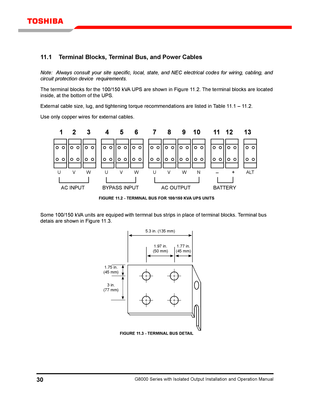
The terminal blocks for the 100/150 kVA UPS are shown in Figure 11.2. The terminal blocks are located inside, at the bottom of the UPS.
External cable size, lug, and tightening torque recommendations are listed in Table 11.1 – 11.2.
Use only copper wires for external cables.
1 | 2 | 3 | 4 | 5 | 6 | 7 | 8 | 9 | 10 | 11 | 12 | 13 | ||||||||||||
|
|
|
|
|
|
|
|
|
|
|
|
|
|
|
|
|
|
|
|
|
|
|
|
|
|
|
|
|
|
|
|
|
|
|
|
|
|
|
|
|
|
|
|
|
|
|
|
|
|
|
|
|
|
|
|
|
|
|
|
|
|
|
|
|
|
|
|
|
|
|
|
|
|
|
|
|
|
|
|
|
|
|
|
|
|
|
|
|
|
|
|
|
|
|
|
|
|
|
|
U | V | W | U | V | W | U | V | W | N | – | + | ALT | ||||||||
|
|
|
|
|
|
|
|
|
|
|
|
|
|
|
|
| ||||
|
|
|
|
|
|
|
|
|
|
|
|
|
|
|
|
| ||||
|
| AC INPUT |
|
| BYPASS INPUT |
|
| AC OUTPUT |
|
| BATTERY |
| ||||||||
|
|
|
|
| FIGURE 11.2 - TERMINAL BUS for 100/150 kVA UPS units |
|
|
| ||||||||||||
Some 100/150 kVA units are equiped with termnal bus strips in place of terminal blocks. Terminal bus detais are shown in Figure 11.3.
5.3 in. (135 mm)
1.97 in. | 1.77 in. | |||
(50 mm) | (45 mm) | |||
|
|
|
|
|
|
|
|
|
|
1.75 in.
(45 mm)
3in.
(77 mm)
figure 11.3 - terminal bus detail
30 | G8000 Series with Isolated Output Installation and Operation Manual |