11 UPS Wiring
Note: Always consult your local and NEC electrical codes for wiring, cabling, and circuit protection devices. requirements.
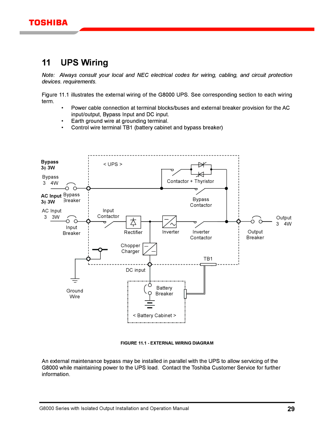
Figure 11.1 illustrates the external wiring of the G8000 UPS. See corresponding section to each wiring term.
•Power cable connection at terminal blocks/buses and external breaker provision for the AC input/output, Bypass Input and DC input.
•Earth ground wire at grounding terminal.
•Control wire terminal TB1 (battery cabinet and bypass breaker)
Bypass 3f 3W
bypass
34w
AC Input bypass | |
3f 3W | breaker |
AC Input
33W
Input
breaker
Ground
wire
< UpS > |
|
|
| Contactor + Thyristor | |
|
| bypass |
Input |
| Contactor |
|
| |
Contactor |
|
|
rectifier | Inverter | Inverter |
|
| Contactor |
Chopper |
|
|
Charger |
|
|
|
| Tb1 |
DC input
battery breaker
< battery Cabinet >
output 3 4w
output
breaker
FIGURE 11.1 - EXTERNAL WIRING DIAGRAM
An external maintenance bypass may be installed in parallel with the UPS to allow servicing of the G8000 while maintaining power to the UPS load. Contact the Toshiba Customer Service for further information.
G8000 Series with Isolated Output Installation and Operation Manual | 29 |