and Operation
Introduction
Viewing ・ Listening
Recording
Set up
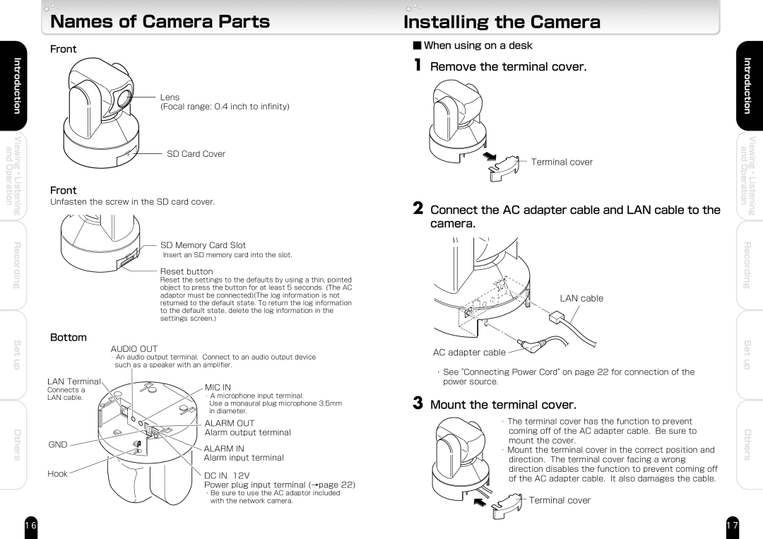
Names of Camera Parts
Front
Lens�
(Focal range: 0.4 inch to infinity)
SD Card Cover
Front
Unfasten the screw in the SD card cover.
SD Memory Card Slot�
Insert an SD memory card into the slot.
 Reset button�
Reset the settings to the defaults by using a thin, pointed � object to press the button for at least 5 seconds. (The AC � adaptor must be connected)(The log information is not � returned to the default state. To return the log information � to the default state, delete the log information in the � settings screen.)
Bottom
AUDIO OUT�
・An audio output terminal. Connect to an audio output device � such as a speaker with an amplifier.
Installing the Camera
■ When using on a desk
1 Remove the terminal cover.
![]() Terminal cover
Terminal cover
2 Connect the AC adapter cable and LAN cable to the camera.
LAN cable
AC adapter cable
・See "Connecting Power Cord" on page 22 for connection of the |
Introduction | |
and | Viewing |
Operation | Listening |
| ・ |
Recording | |
Set up
Others
LAN Terminal�
Connects a �
LAN cable.
GND ![]()
Hook
MIC IN�
・A microphone input terminal. �
Use a monaural plug microphone 3.5mm � in diameter.�
�
ALARM OUT�
Alarm output terminal
ALARM IN�
Alarm input terminal
DC IN 12V�
Power plug input terminal (→page 22) �
・Be sure to use the AC adaptor included � with the network camera.
power source. |
3 Mount the terminal cover.
・The terminal cover has the function to prevent
coming off of the AC adapter cable. Be sure to mount the cover.
・ Mount the terminal cover in the correct position and direction. The terminal cover facing a wrong direction disables the function to prevent coming off of the AC adapter cable. It also damages the cable.
![]()
![]() Terminal cover
Terminal cover
Others
16 | 17 |