Descarga de ar tipo cassete de 1 vias
MMU-AP0071YH,RBC-UY135PGMMU-AP0091YH MMU-AP0121YH
Tipo a cassetta con scarico daria a 1 vie
Modelo de casete de distribución de aire de 1 vías
HFC R410A R22
Adoption of NEW Refrigerant
Sommaire
Shape Usage
Refrigerant piping
Separate sold parts
Part name
Connect the connecting wire correctly
Precautions for Safety
New Refrigerant Air Conditioner Installation
To Disconnect the Appliance from Main Power Supply
Inappropriate grounding may cause electric shock
Precautions for Safety
Installation space
Selection of Installation Place
Removal of transporting rubbers
Installation of Indoor Unit
Selection of Installation Place
Case of wireless type
External view
Wired remote controller RBC-AMT21E
Installation of hanging bolts
Installation of Indoor Unit
Ceiling opening and installation of hanging bolts
How to use the attached installation pattern
Installation of ceiling panel Sold separately
Installation of indoor unit
Drain up
Drain Piping Work
Pipe material/Insulator and size
Connection of drain pipe
Check the draining
Heat insulating of pipe connecting part
When the electric work has finished
When the electric work has not finished
Pipe forming/End positioning
Piping material and dimensions
Refrigerant Piping
Permissible pipe length and permissible height difference
Heat insulating process
Connection of refrigerant pipe
Airtight test/Air purge, etc
Open fully valves of the outdoor unit Gas leak check
Be sure to install an earth leakage breaker
Be sure to connect earth wire. Grounding work
Electric Work
Remote controller wiring
Power supply specifications
Indoor unit power supply
Indoor/Outdoor inter-unit wiring, Central controller wiring
Cable connection
Treating of wiring connecting port
How to remove cover of the electric parts box
Electric Work
Wiring on the ceiling panel
Remote controller wiring
Wiring between indoor and outdoor units
Address setup
Notification
Exchange of applicable control setup
Basic operation procedure for setup exchange
Applicable Controls
To secure better effect of heating
Change of lighting term of filter sign
Group control
Before test operation
How to execute test operation
Case of wired remote controller
Test RUN
Procedure
Case of wireless remote controller
Confirmation of error history
Troubleshooting
Confirmation and check
Check method
Check code list
Terminology
Troubleshooting
TCC-LINK Toshiba Carriea Cominication Link
Error detected by TCC-LINK central control device
Special mention
Display on wired remote controller
Display on sensor part of wireless
New check code
Way Air Discharge Cassette Compact Type
Maintenance
Daily maintenance
Cleaning of air filter
Piè ces vendues sé paré ment
Tuyaux de ré frigé rant
Avertissement
Mesures DE Securite
Pour dé connecter l’appareil du secteur
Ré servé
Mesures DE Securite
Espace requis pour l’installation
Selection DU Lieu D’INSTALLATION
Sur les types sans-fil
Installation DE L’UNITE Interieure
Selection DU Lieu D’INSTALLATION
Enlè vement des caoutchoucs de transport
100 850 400 200 120 140 235 Métal de support
Vue exté rieure
Comment utiliser le gabarit de montage joint
Installation DE L’UNITE Interieure
Installation du boulon de suspension
Installation de la té lé commande vendue sé paré ment
Installation du panneau pour plafond vendu sé paré ment
Installation de l’unité inté rieure
Fixez solidement
Tuyauterie
Tuyauterie/Isolant et dimension
Raccordement du tuyau d’é vacuation
Evacuation ascendante
Isolation thermique des raccords des tuyaux
Lorsque l’installation é lectrique est terminé e
Lorsque l’installation é lectrique n’est pas terminé e
Vé rification de l’é vacuation
Evasement
Tuyauterie et dimensions
Tuyaux DE RÉ Frigé Rant
Mise en forme/Pose définitive des tuyaux
Marge de projection de l’é vasement B Unité mm
Raccordement du tuyau de ré frigé rant
Test d’é tanché ité /Purge d’air, etc
Procé dé de calorifugeage
Assurez-vous de raccorder le fil de terre. Mise à la terre
Travaux D’É Lectricité
Caracté ristiques de l’alimentation é lectrique
Câ bles de la té lé commande *4
Alimentation é lectrique de l’unité inté rieure
Traitement des ports de connexion des câ bles
Travaux D’É Lectricité
Raccordement des câ bles
Comment dé monter le couvercle du boîtier é lectrique
Sché ma de câ blage
Raccordement des té lé commandes
Configuration de l’adresse
Raccordement sur le panneau de plafond
Modification de la configuration de la commande possible
Commandes Utilisables
Procé dure de base pour modifier la configuration
Pour garantir un meilleur chauffage
Commande de groupe
Remarque
Mode d’exé cution d’un essai de fonctionnement
En cas de té lé commande avec fil
Essai DE Fonctionnement
Récepteur Entretoise Vis M4 × 25 2 pièces Encoche
Avec une té lé commande sans-fil
Petite vis
Mé thode de vé rification
DÉ Pannage
Confirmation et vé rification
Confirmation de l’historique de pannes
Terminologie
Liste des codes de vé rification
MG-SW
DÉ Pannage
IPDU, I/F
Mention spé ciale
Affichage sur té lé commande à fil
Affichage sur capteur té lé commande sans-fil
Nouveau code de vé rification
Nettoyage du filtre à air
Entretien
Entretien quotidien
Type compact cassette à 1 voie de refoulement de l’air
Kühlmittel-Leitungssystem
Getrennt erhältliche Teile
Warnung
Sicherheitsvorkehrungen
Vorsicht Trennen des Gerä ts von der Hauptstromversorgung
Sicherheitsvorkehrungen
Vorsicht
Auswahl DES Aufstellungsortes
Platzbedarf
Fü r drahtlose Fernbedienungen
Installation DER Raumeinheit
Auswahl DES Aufstellungsortes
Ausbau der Transportsicherungen
Gerä teansicht
Installation der Fernbedienung getrennt erhä ltlich
Installation DER Raumeinheit
Benutzung der Installationsvorlage
Installation der Aufhä ngebolzen
Installation der Deckenkassette gesondert zu kaufen
Installation der Inneneinheit
Anschluss des Kondensatschlauchs
Rohrmaterial/Isolation und Abmessung
Kondenswasserablauf nach oben
Wä rmeisolierung der Rohrverbindungen
Nach Fertigstellung der Elektroinstallation
Wenn die Elektroinstallation noch nicht fertiggestellt ist
Ablauf ü berprü fen
Biegen und Positionieren
KÜ Hlmittelleitungen
Erlaubte Rohrleitungslä ngen und erlaubte Hö hendifferenzen
Rohrmaterial und Abmessungen
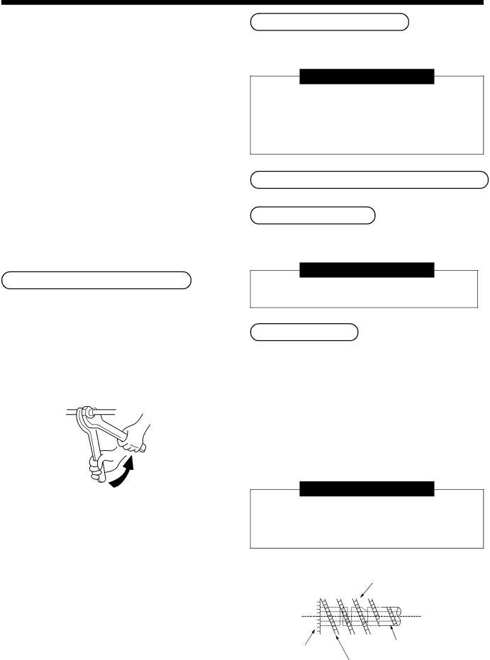
Bö rdelhö he B Einheit mm Starr Kupplung
Anschluss der Kü hlmittelleitung
Dichtetest/Entlü ftung usw
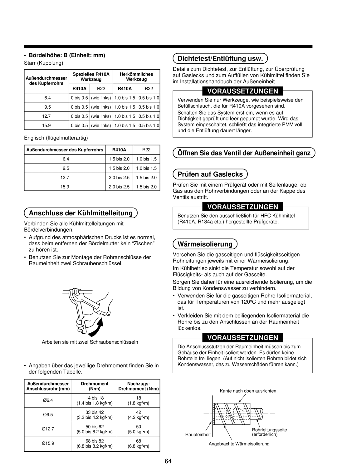
Wä rmeisolierung
Verlegen Sie auch eine Masseleitung. Masse anschließen
Elektroarbeiten
Stromversorgung Raumeinheit
Spezifikation der Stromversorgung
Verkabelung der Fernbedienung
Abdichtung der Kabeldurchfü hrung
Elektroarbeiten
Kabelanschlü sse
Ffnen der Abdeckung des Schaltkastens
Verkabelung des Deckenrahmens
Verkabelung der Fernbedienung
Verbindungskabel zwischen Raum- und Außeneinheit
Adress-Einstellung
Automatische Adressierung
Steuerungsmö Glichkeiten
Hinweise
Nderung der Steuerungsvorgaben
Für den Code in Vorgehensweise 3 geben Sie 01 ein
Nderung der Zeitvorgabe fü r die Filterwarnleuchte
Verbesserung der Heizleistung
Gruppensteuerung
Ablauf des Tests
Testlauf
Hinweis
Vorbereitung
Infrarot-Fernbedienung
Testlauf
Beschreibung
Prü fmethode
Fehlersuche
Bestä tigung und Prü fung
Aufruf des Fehlerspeichers
AI-NET
Liste der Fehlercodes
Fehlersuche
TCC-LINK Toshiba Carrier Communication Link
Fehler durch zentrale Ü berwachung TCC-LINK erkannt
Spezielle Bemerkung
Neuer Prü fcode
Anzeige bei verdrahteter Fernbedienung
Anzeige auf Empfangsteil der Infrarot-Fernbedienung
Wird auf der Fernbedienung
Wartung
Wege-Kassetten-Kompakt-Modell
Tä gliche Wartung Reinigen des Luftfilters
Nome delle parti Forma
Parti da acquistare a parte
Tubazioni del refrigerante
Nome delle parti Forma Utilizzo
Collegare il cavo di connessione in modo corretto
Precauzioni PER LA Sicurezza
Avvertenza
Ttenzione
Una messa a terra non corretta può causare scosse elettriche
Precauzioni PER LA Sicurezza
Spazio per l’installazione
Scelta DEL Posto D’INSTALLAZIONE
Evitare l’installazione nei posti seguenti
Nel caso del tipo via radio
Installazione DELL’UNITÀ Interna
Scelta DEL Posto D’INSTALLAZIONE
Rimozione dei gommini di protezione durante il trasporto
Telecomando via cavo RBC-AMT21E
Vista esterna
Installazione del pannello del soffitto in vendita a parte
Installazione DELL’UNITÀ Interna
Come usare la sagomo per installazione fornita in dotazione
Installazione del bullone di sospensione
Fissare saldamente
Installazione dellunità interna
Scarico
Lavoro PER Tubazione DI Scarico
Materiale per tubazioni/Isolamento e formato
Connessione del tubo di scarico
Se i collegamenti elettrici sono stati completati
Controllare lo scarico
Se i collegamenti elettrici non sono stati completati
Formatura tubi/Posizionamento estremità
Materiale per tubature e dimensioni
Dimensione misuratore dia. svasatura a Unità mm
Tubazioni DEL Refrigerante
Imperial Tipo con dado ad alette
Connessione del tubo del refrigerante
Prove di tenuta d’aria/Sfiato aria, ecc
Procedura per isolamento termico
Collegamenti Elettrici
Installare un interruttore di collegamento a terra
Alimentazione elettrica dell’unità interna
Dati tecnici per alimentazione elettrica
Collegamenti elettrici del telecomando
Collegamento dei cavi
Collegamenti Elettrici
Come trattare la porta di connessione fili
Impostazione dindirizzamento
Schema dei collegamenti elettrici
Posa in opera dei cavi per il telecomando
Collegamenti elettrici fra unità interna e esterna
Indirizzamento automatico
Comandi Applicabili
Avviso
Scambio di impostazioni dei comandi applicabili
Per il codice di voce del passo 3 , specificare
Modifica del tempo di accensione del simbolo del filtro
Per garantire una resa migliore del riscaldamento
Controllo di gruppo
Come avviare il funzionamento di prova
Funzionamento DI Prova
Nota
Prima del funzionamento di prova
Caso di telecomando via radio
Metodo di controllo
Risoluzione DEI Problemi
Conferma della casistica di errori
Conferma e controllo
Terminologia
Lista dei codici di controllo
101
Risoluzione DEI Problemi
102
Display su parte sensore di telecomando via radio
Nuovo codice di controllo
Differenza tra codice di controllo nuovo e sistema corrente
Display su telecomando via cavo
Pulizia del filtro dellaria
Manutenzione
Manutenzione giornaliera
Tipo compatto a cassetta con scarico daria a 1 via
Nombre del componente Cantidad Forma
Componentes vendidos por separado
Tubería de refrigerante
Nombre del componente Cantidad Forma Utilización
Conecte el cable de conexió n correctamente
Precauciones Para SU Seguridad
Precaució N
Advertencia
Precauciones Para SU Seguridad
Espacio de instalació n
Selecció N DEL Lugar DE Instalació N
Evite la instalació n en los siguientes lugares
Selecció N DEL Lugar DE Instalació N
Instalació N DE LA Unidad Interior
En el caso de mando a inalá mbrico
Vista exterior
Instalació n del mando a distancia vendido por separado
Instalació N DE LA Unidad Interior
Có mo utilizar el patró n de instalació n adjunto
Instalació n del perno de suspensió n
Instalació n del panel de techo vendido por separado
Instalació n de la unidad interior
Drenaje ascendente
Canalizació N DE Drenaje
Material del tubo / Aislante y tamañ o
Conexió n del tubo de drenaje
Si ya se ha completado la instalació n elé ctrica
Compruebe el drenaje
Aislamiento té rmico de la parte de conexió n de los tubos
Una vez preparada la canalización de drenaje
Moldeado de los tubos / Posició n final
Material y dimensiones de la tubería
Tubería DE Regrigerante
Longitud del tubo y diferencia de altura permisibles
Margen de proyecció n en el abocinado B unidad mm
Conexió n del tubo de refrigerante
Prueba de hermetizado, purga de aire, etc
Proceso de aislamiento té rmico
Asegú rese de conectar todos los cables. Conexió n a tierra
Instalació N ELÉ Ctrica
Instale un disyuntor de fugas a tierra
Alimentació n elé ctrica de la unidad interior
Especificaciones de la alimentació n elé ctrica
Cableado del mando a distancia
Tratamiento del orificio de conexió n del cableado
Instalació N ELÉ Ctrica
Conexió n de los cables
Có mo extraer la tapa del cuadro elé ctrico
Cableado entre las unidades interior y exterior
Configuració n de las identificaciones
Diagrama del cableado
Cableado del mando a distancia
Controles Aplicables
Cambio en la configuració n de los controles aplicables
Notificació N
Control grupal
Configuració n De la señ al de filtro 0000 Ninguno 0001
Cambiar momento de encendido de la señ al de filtro
Para mejorar el efecto calefactor
En el caso de mando a distancia con cable
Prueba DE Funcionamiento
Antes de llevar a cabo la prueba
Có mo realizar una prueba de funcionamiento
Tornillo pequeño
En el caso de mando a distancia inalá mbrico
Mé todo de verificació n
Resolució N DE Problemas
Confirmació n del historial de errores
Confirmació n y verificació n
Terminología
Lista de có digos de verificació n
127
Resolució N DE Problemas
128
Nuevo có digo de verificació n
Desaparecerá el mensaje
Mantenimiento
Modelo compacto de cassette con descarga de aire de 1 vía
Mantenimiento diario Limpieza del filtro de aire
Nome da peça Quant Forma
Peç as vendidas em separado
Tubagem de refrigerante
Nome da peça Quant Forma Utilização
Instalaçã o de Ar Condicionado de Novo Refrigerante
Precauçõ ES DE Seguranç a
Precauçõ ES
Aviso
133
Evite instalar a unidade nos seguintes locais
Selecçã O do Local DE Instalaçã O
Cuidado
Espaç o de instalaçã o
No caso do tipo sem cabos
Instalaçã O DA Unidade Interior
Selecçã O do Local DE Instalaçã O
Remoçã o das borrachas de transporte
136
Instalaçã o de parafuso de suspensã o
Instalaçã O DA Unidade Interior
Abertura do tecto e instalaçã o de parafusos de suspensã o
Como utilizar o esquema de instalaçã o fornecido
Instalaçã o do painel de tecto vendido separadamente
Instalaçã o da unidade interior
Fixe firmemente
Material
Material dos tubos/Isolante e tamanho
Ligaçã o do tubo de drenagem
Drenagem ascendente
Antes de concluídos os trabalhos de electricidade
Verificar a drenagem
Isolamento té rmico da peç a de ligaçã o do tubo
Depois de concluídos os trabalhos de electricidade
Alargamento
Tubagem DE Refrigerante
Material e dimensõ es de tubagem
Definiçã o da Tubagem Posiçã o dos Extremos
Margem de projecçã o no alargamento B Unidade mm
Ligaçã o do tubo de refrigerante
Teste de hermeticidade/Purga de ar, etc
Processo de isolamento té rmico
Nã o se esqueç a de ligar o cabo de terra. Ligaçã o à terra
Trabalhos DE Electricidade
Alimentaçã o elé ctrica da unidade interior
Especificaçõ es da alimentaçã o elé ctrica
Cabos do controlador remoto
Tratamento da porta de ligaçã o dos cabos
Trabalhos DE Electricidade
Ligaçã o de cabos
Como remover a cobertura da caixa das partes elé ctricas
Definiçã o do endereç o
Diagrama de ligaçõ es
Ligaçõ es do controlador remoto
Ligaçõ es entre as unidades interiores e exteriores
Descriçã o
Troca da configuraçã o de controlo aplicá vel
Controlos Aplicá Veis
Endereç amento automá tico
Controlo de grupo
Configuraçã o
Mude o tempo de iluminaçã o do sinal do filtro
Para garantir um melhor efeito do aquecimento
Como efectuar um teste
Teste DE Funcionamento
Avisos
Antes do teste de funcionamento
Parafuso pequeno
No caso de controlador remoto sem cabos
Procedimento
Mé todo de Verificaçã o
Resoluçã O DE Problemas
Confirmaçã o e verificaçã o
Confirmaçã o de historial de erros
Lista de có digos de erros
153
Resoluçã O DE Problemas
Erro detectado pelo dispositivo de controlo central TCC-LINK
Referê ncia especial
Novo có digo de verificaçã o
Visor no controlador remoto com cabos
Visor na parte do sensor sem cabos
Refrigeraçã o/aquecimento
Manutençã O
Tipo Cassete compacta de Descarga de Ar de 1 vias
Aparecer no controlador remoto, deve proceder
Koelmiddelleidingen
Niet meegeleverde onderdelen
Het apparaat loskoppelen van de netvoeding
Installeren van een airconditioner met een nieuw koelmiddel
LET OP
Waarschuwing
Voorzorgsmaatregelen Voor UW Veiligheid
Installeer de airconditioner niet op de volgende plaatsen
Installatieruimte
Bij een draadloos model
Installatie VAN DE Binnenunit
Keuze VAN DE Locatie Voor DE Installatie
Verwijdering van de transportrubbers
Bekabelde afstandsbediening RBC-AMT21E
Buitenaanzicht
Monteren van de ophangbouten
Installatie VAN DE Binnenunit
Zo gebruikt u het meegeleverde installatiesjabloon
Aanbrengen van de plafondopening en de ophangbouten
Montage van het plafondpaneel niet meegeleverd
Installatie van de binnenunit
Stijgleiding
Afvoerleidingen
Leidingmateriaal/isolatie en afmeting
Aansluiten van de afvoerleiding
Wanneer de elektrische bekabeling niet is aangesloten
Controleer de afvoer
Warmte-isolatie van de pijpaansluiting
Wanneer de elektrische bekabeling is aangesloten
Leidingen buigen Bepalen van het uiteinde van de leidingen
Koelmiddelleidingen
Toegestane leidinglengte en hoogteverschil
Leidingmateriaal en -afmetingen
Uitstekende leidinglengte bij trompen B eenheid mm
Aansluiten van koelmiddelleidingen
Gasdichtheid testen Ontluchten enzovoort
Isoleren
Elektrische Bedrading
Installeer altijd een aardlekschakelaar
Controleer of de aardingsaansluiting is gemonteerd. Aarding
Voeding binnenunit
Voedingspecificaties
Bekabeling voor de afstandsbediening
Kabelaansluitingen
Elektrische Bedrading
Behandeling van de aansluitopening voor de bedrading
Adres instellen
Aansluitschema
Bekabeling van de afstandsbediening
Bekabeling tussen de binnen- en buitenunits
Automatische adressering
Bedieningselementen
Belangrijk
Wijzigen van de instellingen
Groepsbediening
De verwarmingscapaciteit optimaliseren
Tijdstip waarop de
Zo voert u de werkingstest uit
Werkingstest
Opmerking
Voordat u een werkingstest uitvoert
Bij gebruik van een draadloze afstandsbediening
Controlemethode
Storingen Verhelpen
Controles
Storingscodes opslaan
Hulpcode
Storingscodelijst
179
Storingen Verhelpen
180
Nieuwe storingscode
Het luchtfilter reinigen
Onderhoud
Dagelijks onderhoud
Compact model voor inbouw in plafond met 1 uitblaasopening
Óùëçíþóåéò øõêôéêïý ìÝóïõ
ÅîáñôÞìáôá ðïõ ðùëïýíôáé îå÷ùñéóôÜ
Ðñïöõëáîåéó Áóöáëåéáó
Ðñïöõëáîåéó Áóöáëåéáó
×þñïò åãêáôÜóôáóçò
Åðéëïãç ÔÏÕ ×ÙÑÏÕ Åãêáôáóôáóçó
Ãéá ôçí ðåñßðôùóç áóýñìáôïõ ôýðïõ
Áöáßñåóç ëÜóôé÷ùí ìåôáöïñÜò
ÅîùôåñéêÞ üøç
395
ÅãêáôÜóôáóç ôïõ ôçëå÷åéñéóôçñßïõ Ðùëåßôáé îå÷ùñéóôÜ
¢íïéãìá ïñïöÞò êáé åãêáôÜóôáóç ôùí ìðïõëïíéþí áíÜñôçóçò
Ðþò íá ÷ñçóéìïðïéÞóåôå ôï ðñïóáñôçìÝíï ðñüôõðï åãêáôÜóôáóçò
ÅãêáôÜóôáóç ôïõ ìðïõëïíéïý áíÜñôçóçò
Ðùëåßôáé îå÷ùñéóôÜ
ÅãêáôÜóôáóç ôçò åóùôåñéêÞò ìïíÜäáò
‹Ù˘ÎÂıÒ‹ÙÔı
ÅãêáôÜóôáóç ôïõ öáôíþìáôïò ïñïöÞò
ÁðïóôñÜããéóç
Óýíäåóç óùëÞíá áðïóôñÜããéóçò
Èåñìïìüíùóç ôïõ ôìÞìáôïò óýíäåóçò ôïõ óùëÞíá
¸ëåã÷ïò ôçò áðïóôñÜããéóçò
¸ Ô ı
Õëéêü êáé äéáóôÜóåéò óùëÞíùóçò
Åðéôñåðüìåíï ìÞêïò óùëÞíá êáé åðéôñåðüìåíç äéáöïñÜ ýøïõò
Ìïñöïðïßçóç óùëÞíùí / ÈÝóç Üêñùí
ÄïêéìÞ áåñïóôåãáíüôçôáò / ÅêêÝíùóç áÝñá, êëð
Óýíäåóç ôïõ óùëÞíá áðïóôñÜããéóçò
Äéáäéêáóßá èåñìïìüíùóçò
$ Çëåêôñéêç Åñãáóéá
Ðáñï÷Þ ñåýìáôïò ôçò åóùôåñéêÞò ìïíÜäáò
ÐñïäéáãñáöÝò ðáñï÷Þò ñåýìáôïò
Ðþò íá áöáéñÝóôå ôï êÜëõììá ôïõ çëåêôñéêïý êïõôéïý
Óýíäåóç êáëùäßùí
×åéñéóìüò ôçò èýñáò ôçò êáëùäßùóçò óýíäåóçò
Êáëùäßùóç óôï öÜôíùìá ôçò ïñïöÞò
Êáëùäßùóç ôçëå÷åéñéóôçñßïõ
Êáëùäßùóç ìåôáîý åóùôåñéêÞò êáé åîùôåñéêÞò ìïíÜäáò
Ñýèìéóç ôçò äéåýèõíóçò
ÁëëáãÞ ñõèìßóåùí åöáñìüóéìùí åíôïëþí
Åöáñìïóéìïé ÅËÅÃ×ÏÉ
Ãéá íá åîáóöáëßóåôå êáëýôåñá áðïôåëÝóìáôá óôç èÝñìáíóç
ÁëëáãÞ ôïõ ÷ñüíïõ áíÜììáôïò ôïõ óÞìáôïò ôïõ ößëôñïõ
Ïìáäéêüò Ýëåã÷ïò
Ðþò íá êÜíåôå ôç äïêéìÞ ëåéôïõñãßáò
Ðñéí ôç äéáäéêáóßá äïêéìÞò
202
Åðéâåâáßùóç éóôïñéêïý óöáëìÜôùí
Åðéâåâáßùóç êáé Ýëåã÷ïò
ÌÝèïäïò åëÝã÷ïõ
Ïñïëïãßá
Ëßóôá êùäéêþí åëÝã÷ïõ
Áíôéìåôùðéóç Ðñïâëçìáôùí
206
Ïèüíç óå åíóýñìáôï ôçëå÷åéñéóôÞñéï
ÍÝïò êùäéêüò åëÝã÷ïõ
Ôýðïò êáóÝôáò êüìðáêô åêñïÞò áÝñá ìßáò êáôåýèõíóçò
ÊáèçìåñéíÞ óõíôÞñçóç
Check of Concentration Limit
Indoor unit setup check sheet
Confirmation of Indoor Unit Setup
EH99832901