INSTALLATION
NON-SEPARATE INSTALLATION
The
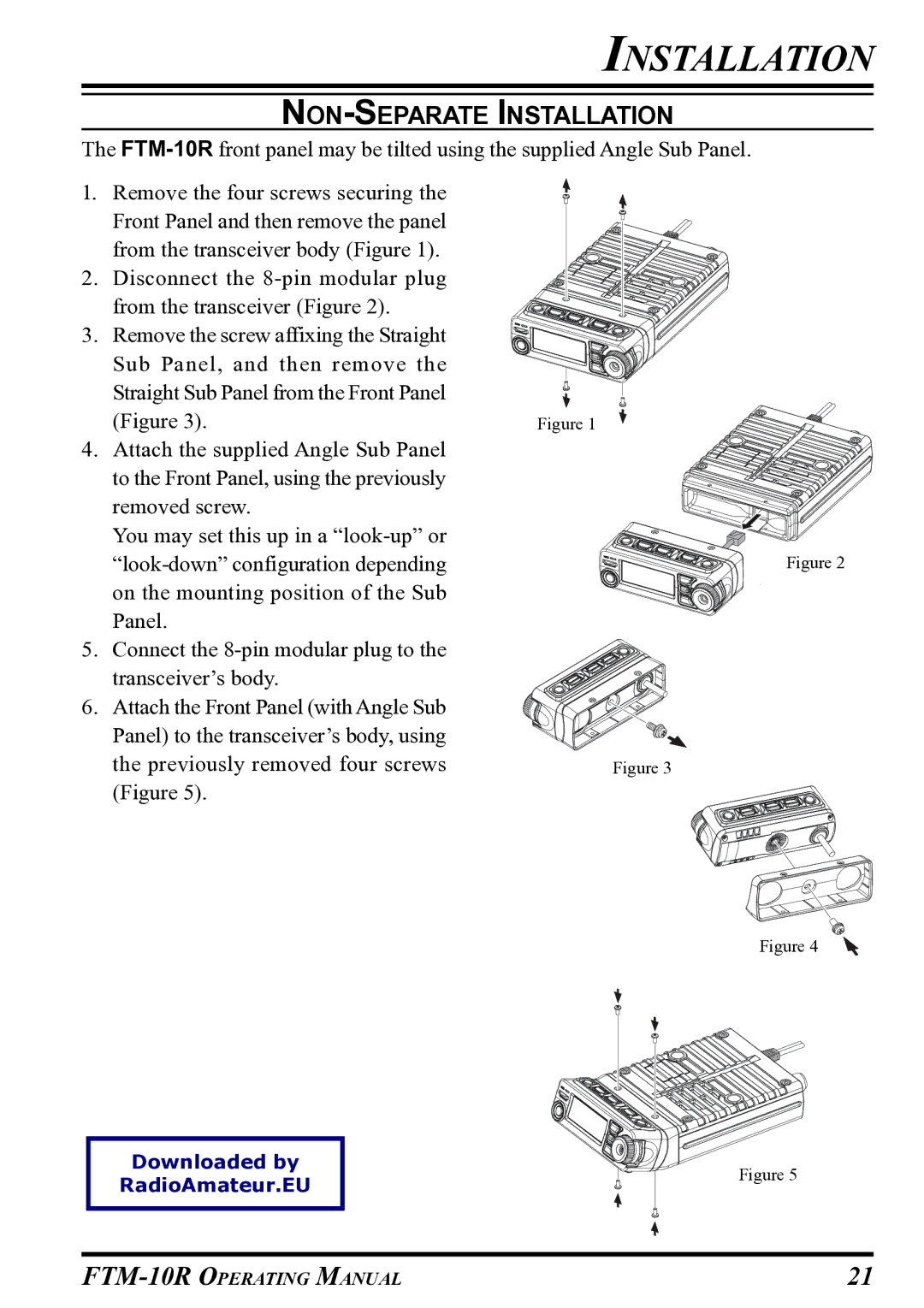
1.Remove the four screws securing the Front Panel and then remove the panel from the transceiver body (Figure 1).
2.Disconnect the
3.Remove the screw affixing the Straight Sub Panel, and then remove the Straight Sub Panel from the Front Panel (Figure 3).
4.Attach the supplied Angle Sub Panel to the Front Panel, using the previously removed screw.
You may set this up in a
5.Connect the
6.Attach the Front Panel (with Angle Sub Panel) to the transceiver’s body, using the previously removed four screws (Figure 5).
Figure 1
Figure 2
Figure 3
Figure 4
Downloaded by
RadioAmateur.EU
Figure 5
21 |