CONNECTIONS
Connecting the power cable
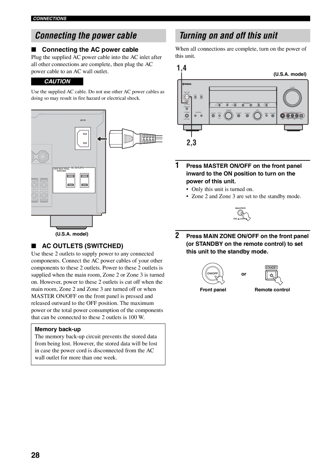
■Connecting the AC power cable
Plug the supplied AC power cable into the AC inlet after all other connections are complete, then plug the AC power cable to an AC wall outlet.
CAUTION
Use the supplied AC cable. Do not use other AC power cables as doing so may result in fire hazard or electrical shock.
AC IN
Turning on and off this unit
When all connections are complete, turn on the power of this unit.
1,4
(U.S.A. model)
VOLUME
MAIN ZONE
ON/OFF |
|
|
|
|
|
| ON/OFF | ON/OFF |
|
|
|
MASTER |
|
|
|
|
|
ON :OFF |
|
|
|
|
|
OPTIMIZER MIC |
|
|
|
|
|
|
|
| PROGRAM |
| INPUT |
PHONES | SPEAKERS |
|
| VIDEO AUX | |
|
| PURE DIRECT STRAIGHT | TONE CONTROL | AUDIO SELECT | MULTI CH ZONE CONTROL |
|
|
|
|
| INPUT |
SILENT CINEMA |
|
|
|
|
|
100W MAX.TOTAL | AC OUTLETS |
SWITCHED |
|
2,3
1Press MASTER ON/OFF on the front panel inward to the ON position to turn on the power of this unit.
•Only this unit is turned on.
•Zone 2 and Zone 3 are set to the standby mode.
MASTER
ON ![]() OFF
OFF ![]()
(U.S.A. model)
■AC OUTLETS (SWITCHED)
Use these 2 outlets to supply power to any connected components. Connect the AC power cables of your other components to these 2 outlets. Power to these 2 outlets is supplied when the main room, Zone 2 or Zone 3 is turned on. However, power to these 2 outlets is cut off when the main room, Zone 2 and Zone 3 are turned off or when MASTER ON/OFF on the front panel is pressed and released outward to the OFF position. The maximum power or the total power consumption of the components that can be connected to these 2 outlets is 100 W.
Memory back-up
The memory
2Press MAIN ZONE ON/OFF on the front panel (or STANDBY on the remote control) to set this unit to the standby mode.
STANDBY
ON/OFFor
Front panel | Remote control |
28