Master Section | 7 |
1
2![]()
3
4
Master Section
0 | 10 | 0 | 10 |
|
1 | 2 | 1 | 2 |
|
GROUP ASSIGN | GROUP ASSIGN |
| ||
3 | 4 | 3 | 4 |
|
GROUP |
| CUE |
| |
MASTER | MASTER |
| ||
1 |
|
|
|
|
|
|
|
| 5 |
0 | 10 | 0 | 10 |
|
|
|
| ||
|
| CUE MIX |
| |
|
| TO STEREO | 6 | |
2 |
|
|
| |
|
|
|
| |
0 | 10 | MONITOR |
| |
|
| SELECT |
| |
3 |
|
| 2TR IN |
|
|
|
|
| |
0 | 10 | 1 | 3 |
|
|
|
| ||
|
| GROUP |
| |
4 |
| 2 | 4 | 7 |
|
| STEREO |
| |
0 | 10 |
| CUE |
|
MONITOR
LEVEL
8
|
| MIN |
| MAX | |||
10 |
| 10 |
|
|
| ||
|
|
| |||||
9 |
| 9 |
|
|
| ||
8 |
| 8 |
|
|
| ||
|
|
|
| ||||
7 |
| 7 |
|
|
| ||
|
|
|
| ||||
|
|
|
| ||||
|
|
|
| ||||
6 |
| 6 |
|
|
| ||
5 |
| 5 |
|
|
| ||
4 |
| 4 |
|
|
| ||
3 |
| 3 |
|
|
| ||
2 |
| 2 |
|
|
| ||
1 |
| 1 |
|
|
| ||
0 |
|
| 0 |
|
|
| |
|
|
|
| ||||
|
|
|
|
|
|
|
|
|
|
|
|
|
|
|
|
STEREO
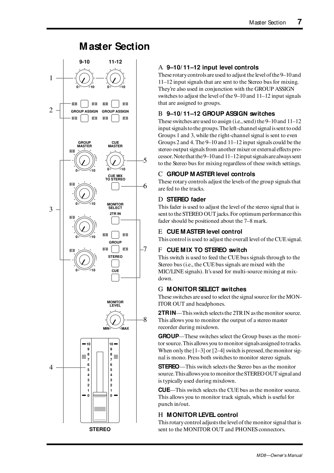
A 9–10/11–12 input level controls
These rotary controls are used to adjust the level of the
B 9–10/11–12 GROUP ASSIGN switches
These switches are used to assign (i.e., send) the
C GROUP MASTER level controls
These rotary controls adjust the levels of the group signals that are fed to the tracks.
D STEREO fader
This fader is used to adjust the level of the stereo signal that is sent to the STEREO OUT jacks. For optimum performance this fader should be positioned about the
E CUE MASTER level control
This control is used to adjust the overall level of the CUE signal.
F CUE MIX TO STEREO switch
This switch is used to feed the CUE bus signals through to the Stereo bus (i.e., the CUE bus signals are mixed with the MIC/LINE signals). It’s used for
G MONITOR SELECT switches
These switches are used to select the signal source for the MON- ITOR OUT and headphones.
2TR
H MONITOR LEVEL control
This rotary control adjusts the level of the monitor signal that is sent to the MONITOR OUT and PHONES connectors.
