18 The First Session
Making the Connections (GRP & DIR)
1.Connect a sound source to MIC/LINE INPUT 1.
If you are using a condenser microphone, set PHANTOM switch to ON to turn on phantom powering.
2.Set the [FLIP] switch on Input Channel 1 to MIC/LINE.
3.If you connect a
4.Proceed to GRP Method or DIR Method.
GRP Method
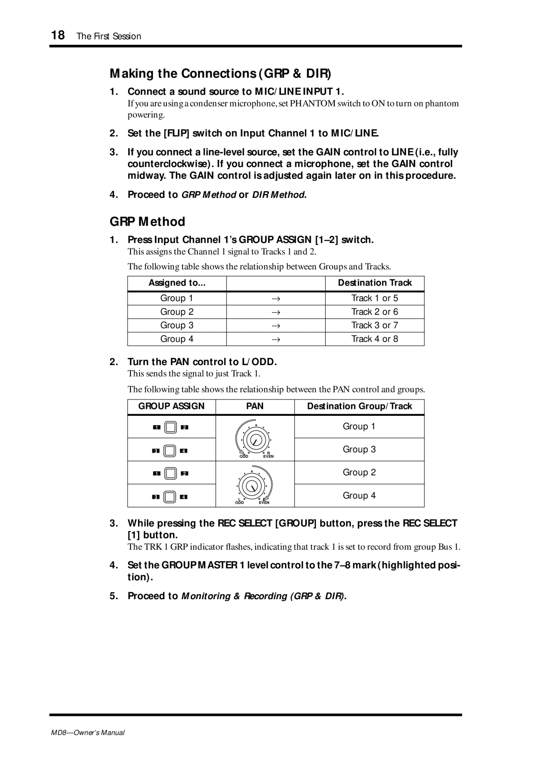
1.Press Input Channel 1’s GROUP ASSIGN [1–2] switch.
This assigns the Channel 1 signal to Tracks 1 and 2.
The following table shows the relationship between Groups and Tracks.
Assigned to... |
| Destination Track |
|
|
|
Group 1 | → | Track 1 or 5 |
|
|
|
Group 2 | → | Track 2 or 6 |
|
|
|
Group 3 | → | Track 3 or 7 |
|
|
|
Group 4 | → | Track 4 or 8 |
|
|
|
2.Turn the PAN control to L/ODD.
This sends the signal to just Track 1.
The following table shows the relationship between the PAN control and groups.
GROUP ASSIGN |
| PAN | Destination Group/Track | ||
1 | 2 |
|
|
| Group 1 |
3 | 4 | L |
| R | Group 3 |
|
| ODD | EVEN |
| |
1 | 2 |
|
|
| Group 2 |
3 | 4 | L |
| R | Group 4 |
|
| ODD |
| EVEN |
|
3. While pressing the REC SELECT [GROUP] button, press the REC SELECT [1] button.
The TRK 1 GRP indicator flashes, indicating that track 1 is set to record from group Bus 1.
4.Set the GROUP MASTER 1 level control to the
5.Proceed to Monitoring & Recording (GRP & DIR).
